SSI UPDATE
THE HIGH FRONTIER NEWSLETTER
SPACE STUDIES INSTITUTE
PRINCETON, NEW JERSEY
VOLUME XXI ISSUE 3
JULY/AUGUST/SEPTEMBER 1995
ABOUT THIS ISSUE
Conference Report and Summary: This issue includes a comprehensive summary of SSI’s recent Conference on Space Manufacturing. The feature includes a short summary of each session, a complete listing of papers and authors, a brief description of each paper and pictures from key presentations. Details for ordering proceedings, audio tapes and video tapes appear on page 6.
DCX Update: A short follow-up article on the DCX featured in the November/December 1993 issue appears on page 8.
Lunar Prospector: The Lunar Prospector, originally designed with SSI support, was chosen by NASA to be launched to the Moon in June, 1997. The total program cost is estimated at $59 million, which was recently approved. We will keep you informed on the progress of this important project through construction, launch and mission phases (page 7). Highlights of the history of the Lunar Prospector appear on page 8.
Solar Power Satellites: A paper by Eric Flint, “Thin-Film Disc-Shaped Large Space Structures (Sunsat or Solar Sail): A Proposed Construction/Assembly Method,” appears on page 9. Flint is an SSI volunteer researcher and received much praise at the recent conference from other participants for his work on this project.
CONNECTING TO SSI’S WORLD WIDE WEB SERVER
With the help of Senior Associate Robert Lentz (XXXX@rossi.astro.nwu.edu), SSI has set up a World Wide Web home page. To connect, open a web browser (like Lynx, Mosaic, or Netscape), choose “Open URL” or “Open Location” from a menu or a list of commands. Then enter “http://www.astro.nwu.edu/lentz/ space/ssi” and press return. Within a few seconds, you will connect to SSI’s Home page, from which you can get information about SSI, or connect to other related sites. If you have difficulty with these instructions, contact your service provider, since there are many different methods of connecting. If this doesn’t work, send us a note, and one of our staff will help you.
SUMMARY OF THE SSI CONFERENCE ON SPACE MANUFACTURING
Princeton, May 4-7, 1995
This conference is the twelfth in a series which began in 1974. This year’s conference is dedicated to the memory of Dr. Gerard K. O’Neill, founder of Space Studies Institute, author of “The High Frontier” and organizer of the first several conferences. He was an active participant of all the conference events until his death in 1992.
WELCOMING REMARKS:
George Friedman
Space Studies Institute
INTRODUCTORY REMARKS:
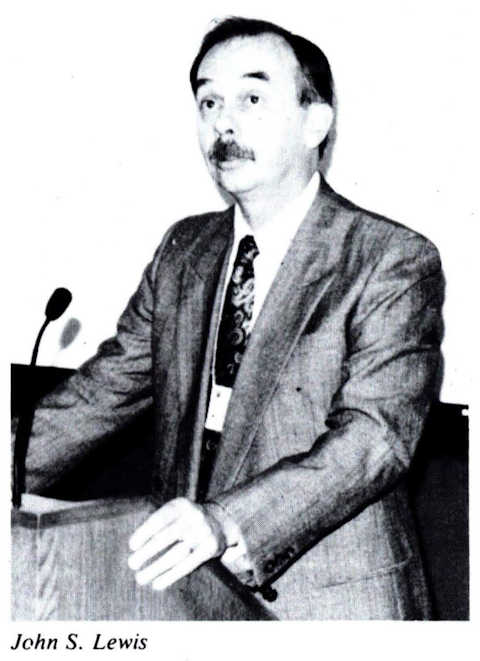
John S. Lewis
University of Arizona
KEYNOTE ADDRESS:
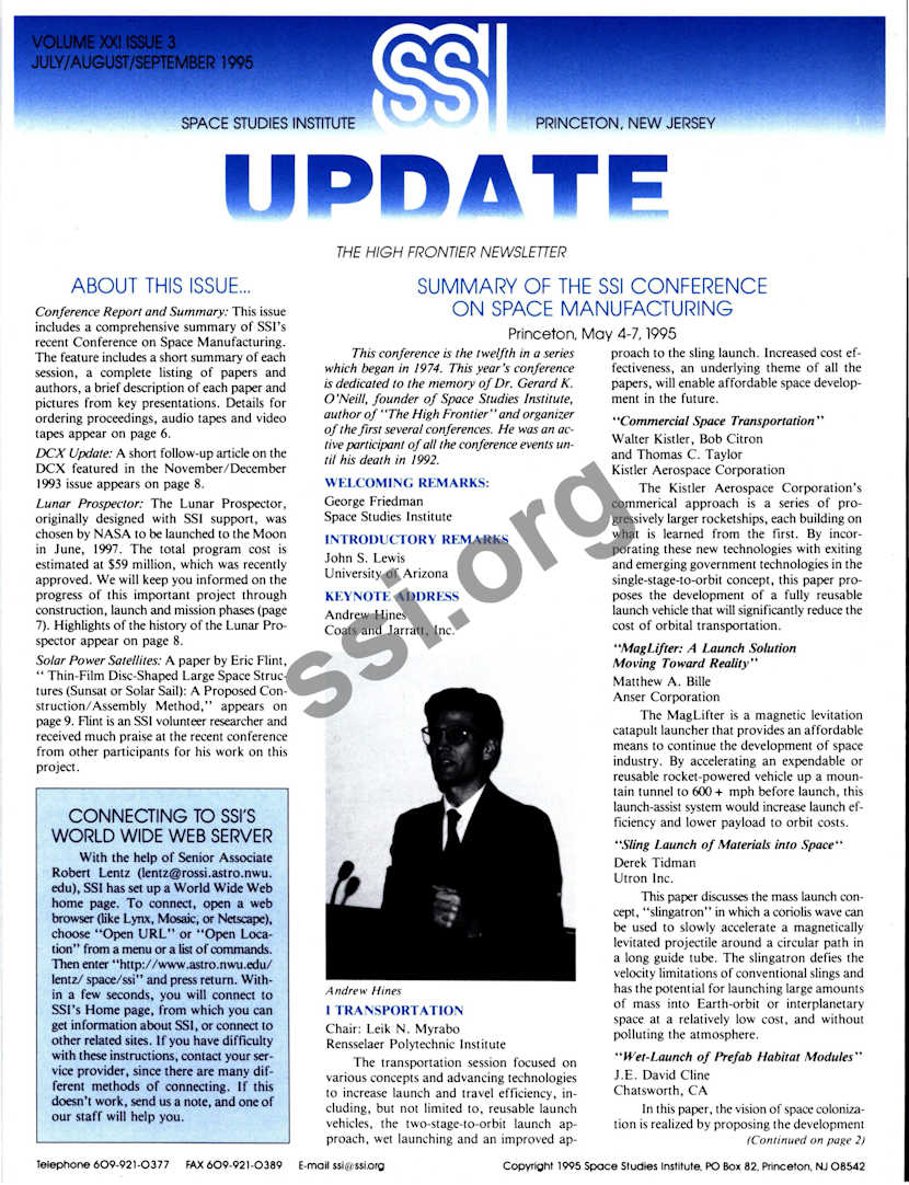
Andrew Hines
Coats and Jarratt, Inc.

I TRANSPORTATION
Chair: Leik N. Myrabo
Rensselaer Polytechnic Institute
The transportation session focused on various concepts and advancing technologies to increase launch and travel efficiency, including, but not limited to, reusable launch vehicles, the two-stage-to-orbit launch approach, wet launching and an improved approach to the sling launch. Increased cost effectiveness, an underlying theme of all the papers, will enable affordable space development in the future.
“Commercial Space Transportation”
Walter Kistler, Bob Citron and Thomas C. Taylor
Kistler Aerospace Corporation
The Kistler Aerospace Corporation’s commerical approach is a series of progressively larger rocketships, each building on what is learned from the first. By incorporating these new technologies with exiting and emerging government technologies in the single-stage-to-orbit concept, this paper proposes the development of a fully reusable launch vehicle that will significantly reduce the cost of orbital transportation.
“MagLifter: A Launch Solution Moving Toward Reality”
Matthew A. Bille
Anser Corporation
The MagLifter is a magnetic levitation catapult launcher that provides an affordable means to continue the development of space industry. By accelerating an expendable or reusable rocket-powered vehicle up a mountain tunnel to 600+ mph before launch, this launch-assist system would increase launch efficiency and lower payload to orbit costs.
“Sling Launch of Materials into Space”
Derek Tidman
Utron Inc.
This paper discusses the mass launch concept, “slingatron” in which a coriolis wave can be used to slowly accelerate a magnetically levitated projectile around a circular path in a long guide tube. The slingatron defies the velocity limitations of conventional slings and has the potential for launching large amounts of mass into Earth-orbit or interplanetary space at a relatively low cost, and without polluting the atmosphere.
“Wet-Launch of Prefab Habitat Modules”
J.E. David Cline
Chatsworth, CA
In this paper, the vision of space colonization is realized by proposing the development of dual-purpose space modules. With the development of modular wet-launch technology, a segment of a prefabricated habitat would serve first as a temporary fuel tank during launch; then, once at its orbital site, this structure would become a living space. By launching multiple prefab structures and joining them together at their orbital site, this technology launches us towards the reality of future space living.
“Mass Driver Launch of Crewless, Reusable Vehicles with ‘Vacuum’-Path Laser to LEO”
Thomas M. Morse
Mooresville, NC
With the goal to develop a launch vehicle to move cargo from Earth to low-Earthorbit, this paper proposes the development of a laser solar-powered electromagnetic launcher that is economical, reliable, and reusable. Also discussed are launch and landing alternatives for such a vehicle, as well as ways to “add backbone” to the launch vehicle.
II ASTEROIDS AND NON-TERRESTRIAL MATERIALS
Chair: George Friedman
Space Studies Institute

In order to detect, defend against, and exploit asteroids and near-Earth objects, we need to know more about them. This session focuses on the threat of asteroids and the exploration of near-Earth objects. Discussion also includes the potential development of lunar surfaces. Here the need for aluminum for construction purposes and water supply for human habitation in space are illustrated. Concepts are presented that provide solutions to these technological stumbling blocks, with the conclusion that, with technological advances, space development, exploration, and settlement will be a part of the future.
“Adroitly Avoiding Asteroids! Clobber, Coax or Consume?”
Alan J. Willoughby and Melissa McGuire
Analex Corporation
The idea of turning threatening asteroids into useful products to prevent them from colliding with Earth has been reinforced by recent analysis of the tremendous profit potential of their precious metals. “Consumption” is a third major option for preventing asteroid disasters. The other options are to use nuclear weapons (“clobber”) or to gradually propel (“coax”) the threatening body into a slightly different orbit. The objective of this paper is to put the asteroid threat, its potential solutions and space resources into a clear perspective.
“Near-Earth Asteroid Rendezvous Project-First Launch of the NASA Discovery Program”
Andrew F. Cheng and A.G. Santo
The Johns Hopkins University
Applied Physics Laboratory
With the Near Earth Asteroid Returned Sample (NEAR) mission scheduled to launch in February 1996, this paper presents an overview of the NEAR mission, spacecraft, and instruments. The NEAR mission, the first of its type, will orbit a large and important nearEarth asteroid for about one year, and will allow detailed studies of an S-asteroid (the most common type among near-Earth asteroids). This approach to space studies provides a low-cost, timely access to plantetary information.
“Conceptual Design of the Near Earth Asteroid Returned Sample (NEARS) Mission”
David Kusnierkiewicz, A.F. Cheng, J.V. McAdams, and S.R. Vernon
The Johns Hopkins University
Applied Physics Laboratory
From a re-entry capsule on a Near Earth Asteroid Returned Sample (NEARS) mission a pyrotechnic sampling device will make momentary contact with an asteroid surface before returning to Earth. To satisfy the objectives of the mission, up to 6 bulk samples from a near-Earth C-type asteroid will need to be returned to Earth for laboratory analysis. This paper summarizes the objectives of the NEARS mission, its instrument payload, and spacecraft design.
“Selective Evaporation of Lunar Oxide Components”
Rudolf Keller and David B. Stofesky
EMEC Consultants
Aluminum is an essential structural material to be used in advanced space missions and construction of solar power satellites. In order to continue to expand our lunar horizons, it is necessary to develop a means to prepare aluminum from indigenous lunar material. This paper summarizes the concept, experimental technique and results that support the concept of the lunar vacuum to produce both oxygen and metals.
“Exploitation of Space Oases”
David L. Kuck
Oracle, AZ
“With water everything is possible! Without water nothing is possible!” The theme of this paper is first exploitation of water resources, and second, exploration. The targets for exploitation are Earth-approaching comets and asteroids. In his paper, David Kuck outlines the how’s and why’s of a drilling system to tap into and use the much needed supply of water that will make future space colonization possible.
Increasing Recognition of Near-Earth Objects (NEOs)”
George Friedman
Space Studies Institute
Although many engineering and management challenges lie ahead, it is likely that the discovery rate of asteroids and comets will be accelerated at least ten-fold in order to warn humanity of impending impacts and provide time to mitigate the risk. In this paper, Friedman discusses the observation, accuracy and probability of NEO detection programs and urges accelerated long-range studies and plans on a total planetary defense system.
III BIOMEDICAL
Chair: Shaun B. Jones
Advanced Research Projects Agency
The Biomedical session takes a look at some environmental issues of space habitation, from the theory of a sociological organization to guide space living, to the concept of architecture that works with the characteristics of artificial gravity in the construction of a space colony. This session also explores the potential of telepresence surgery.
“Methexis and Extraterrestrial Medicine”
Erik T. Paterson and T.T. Paterson
Erik T. Patterson Medical Services, Inc.
In order for human beings to flourish in space, it is necessary to look beyond engineering studies and focus on human needs for long-term survival in space. Two aspects considered in this paper are the administrative and the medical and their interface. Summarized here, the life studies of the late T.T. Paterson focus on Methexis, the fundamentals of human roles in any organization, on Earth or in space. Also discussed is Erik Paterson’s concept of Extra-Terrestrial Medicine (ETM) and its potential for significant impact on current healthcare economics.
“The Architecture of Artificial Gravity: Theory, Form and Function in the
High Frontier”
Theodore W. Hall
Chinese University of Hong Kong
Studies have found differences between natural and artificial gravity. Using those differences, this paper examines: the role of gravity in architectural design; the extensions of architectural theory needed to accommodate the peculiarities of artificial gravity; and the appropriateness of certain space colony architecture that depicts an Earth-like design. Theodore Hall questions whether architecture should deny the differences between natural and artificial gravity, or respond to them and incorporate them into the design.
“Surgery 2001”
Shaun B. Jones
Advanced Research Projects Agency
Riding on the wave of virtual reality and the in formation superhighway, medicine has received its wake-up call. The time is now for physicians to take advantage of advancing technologies and look into the 21st century with great expectations. This paper discusses various telepresence systems; robotics that enhance skills beyond the limitations of the human body; computer-aided instruction and virtual reality that transcend current medical practices. The technologies now being developed will dissolve time and space and make it possible for patients to receive superior care, whether on Earth or in space.
IV ROBOTICS
Chair: William Whittaker
Robotics Institute
Carnegie Mellon University
This session addresses robotic systems that effect various mission stages from launch preparation through the mission. From construction on a launch pad, to human assisted robots in remote locations that provide experimental data, advancing technology in the field of robotics will enable cost effective space exploration with minimal human risk.
Ranger Telerobotic Flight Experiment Program Update”
Joseph D. Graves
University of Maryland
In the future the demand for space operations is projected to increase dramatically, requiring the development of innovative ways to accomplish work in space. The Ranger Telerobotic Flight Experiment is designed to demonstrate in the near term the ability of a free flying telerobotic system to perform many required operational tasks including on-orbit refueling, instrumentation package replacement, and deployment of failed mechanisms such as antennae and solar arrays. In this paper Joseph Graves discusses the mission profile and status of the Ranger TFX.
“Kilauea: A Terrestrial Analogue for Studying the Use of Rovers in Planetary Science”
Hans Thomas
RECOM Technologies, Inc.
Butler Hine
NASA Ames Research Center
John Garvey
McDonnel Douglas Aerospace Corporation
The Kilauea volcano, located on the big island of Hawaii, represents a premier terrestrial analogue for the study of planetary volcanism. Studies of Kilauea have aided planetary scientists in understanding volcanism on the Moon, Venus, and Io (Jupiter’s moon), as well as the Earth. Tests conducted at Kilauea in February 1995 represent the first time a state of the art, fully integrated rover chassis, teamed with advanced ground control software, has been placed in the hands of a science team, allowing them to perform remote science in a manner similar to that of an actual planetary mission. This paper details the insight gleaned from these tests and the ultimate goal of sending sophisticated robotic rovers to the Moon and Mars to study planetary volcanism.
“Mixed-Mode Control of Navigation for a Lunar Rover”
Reid Simmons, Eric Krotkov,
Lonnie Chrisman, Fabio Cozrnan,
Richard Goodwin, Martial Hebert,
Guillermo Heredia, Sven Koenig, Pat Muir,
Yoshikazu Shinoda, William Whitaker
The Robotics Institute
Carnegie Mellon University
The question of how to navigate is critically important to the success of any lunar rover mission. While humans typically have good judgement about which routes to take, they often get fatigued and disoriented when teleoperating rovers with time delay. On the other hand, while autonomous systems can produce safe and reliable navigation, they tend to be myopic. This paper investigates mixedmode methods of control that combine the strengths of humans and rovers.
“A Robotic Expedition for Mass Interaction on the Moon”
Lalitesh Katragadda
The Robotics Institute
Carnegie Mellon University
David Gump
Luna Corp
The Moon is an accessible planetary body with possible commercial agenda for exploration, manufacturing, and habitation. Carnegie Mellon and LunaCorp have proposed a robotic lunar mission motivated by agenda of exploration and mass participation. The mission is an expedition to five historic landing sites starting with Apollo 11. Design requirements, public participation through tele-experience, and space robotic capability are discussed in this paper.
V ADVANCED TECHNOLOGIES
Chair: Steven Vetter
Molecular Manufacturing, Inc.
Looking beyond current technologies, advanced technologies facilitate the goals of today’s scientists by finding more cost-effective methods to gain access to space. In this session discussion includes the concept of and preparation for molecular nanotechnology.
“A Reference Design for a Near Term Low-Earth Orbit Commercial Business Park”
Charles J. Lauer
University of Michigan
Joseph Hopkins, Dana Andrews
Boeing Aerospace Corporation
Hugh Kelso
Orbital Properties, Ltd.
Assuming the successful development of affordable private sector launch capabilities, this paper outlines the means for a major commercial expansion into space. The discussion includes such topics as: module outfitting concepts to support manufacturing and tourism, basic launch requirements, and marketing issues for orbital business parks. It concludes with a look at similar commercial developments, initially government funded, that have provided significant job growth and stimulate investments from the private sector.
“Bootstrapping Space Communities With Micro Rovers and High-Tensile Boot Laces (Tethers)”
Bruce Mackenzie
Draper Corporation
“Bootstrapping” is the key to starting space settlement: Start with the least expensive manufacturing and transportation system which can then use materials in space to increase its own capacity. This paper proposes tethers, miniature rovers and regolith rockets for low cost transportation to allow us to optimize the locations of manufacturing. Initial manufacturing is in LEO where machinery and workers are easier to support. The system grows by producing. Growth may be self-financing all without the expense of sending people to the lunar surface.
“Minimizing the Initial Space Manufacturing Base”
Steven Vetter
Molecular Manufacturing, Inc.
One of the most expensive parts of any plan to open the High Frontier is transporting the initial mining and manufacturing facilities from Earth. The cost is in proportion to the mass of these facilities. This paper examines the limits encountered when one attempts to shrink the mass of the initial base. The conclusion is that the only real limit is at the molecular level. The paper combines research in minimizing the mass of a solar power satellite, robotics, self-replicating systems and other related technologies to realize that building facilities from the atom up will facilitate the goal to open the high frontier.
“Planning Scenarios for Space Development”
Thomas L. McKendree
Molecular Manufacturing Shortcut Group
This paper examines two extreme scenarios that could occur if we begin developing molecular nanotechnology (MNT) at roughly the same time as we try to open the high frontier. The first scenario presents a “slow and planned” approach. In the first case, there is so much planning time that space development is over regulated and controlled by the government. The second scenario, where MNT comes “sooner” than expected, illustrates the chaos that could occur if there are not yet any “rules of the road” guiding space development. By examining the two scenarios, it becomes evident that proper planning in coordination with MNT is critical.
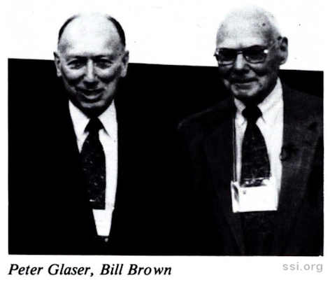
VI WIRELESS POWER TRANSMISSION
Chair: Peter Glaser
Arthur D. Little Company
This session summarizes the importance of solar energy from space and its relationship to wireless power transmission. Papers include methodology to supply energy to remote locations around the Earth, the potential impact of thin-film technology, the efficiency and safety of wireless power transmission, and the eventual development of solar power satellites and a lunar power system.
“Power from Space:
The Imperatives of Commercialization”
Mary Woodell
Bivings Woodell, Inc.
Recognizing that microwave technology in space has proven to be a viable and apparently safe way to generate energy, this paper examines the commercial considerations of this technology. Looking at the components of market demand, (i.e., need, safety, benefits, value, and means) the challenges and commercial potential of wireless power transmission (WPT) as an alternative energy source are considered. The conclusion being that successful commercialization will require a coalition of people whose common pursuit is to advance wireless power transmission.
“The SABER Microwave Powered Helicopter Project”
Shawn Houston, Eric Ruse, John Riedman and Joe Hawkins
University of Alaska
William C. Brown
MPT Systems
By using solar power satellites, wireless power transmission (WPT) has the potential to supply the Earth with low-cost energy. The goal of the SABER helicopter system is to design and construct a WPT demonstration. This paper details two key components needed for an effective WPT system and the rectenna array. This paper also explores the other major subsystems of a WPT: airframe, propulsion, sensor and controller. Each of the components can be independently adapted to a larger WPT system.
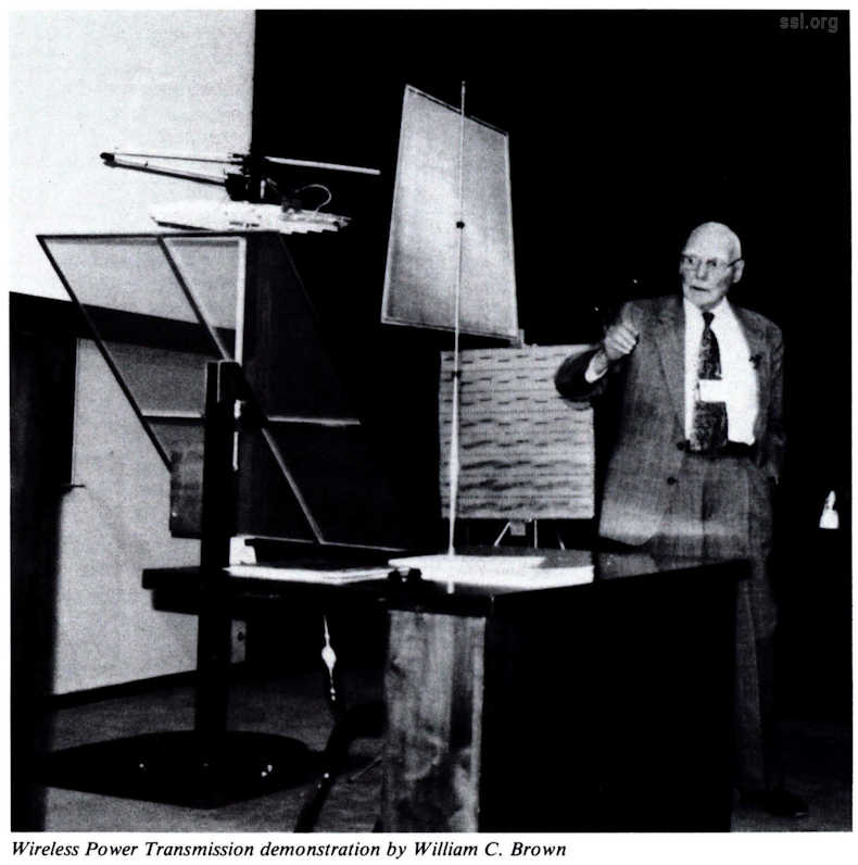
“Current Demonstrations of Wireless Power Transmission and Their Relationship to the Solar Power Satellite”
William C. Brown
MPT Systems
Joseph Hawkins
University of Alaska

This paper examines the strong interactive relationship between advances in wireless power transmission (WPT) technology and Solar Power Satellites (SPS). WPT technology, as applied to high-altitude aircraft, and the SPS are discussed, since both use a new transmitter technology – ESP AM (electronically steerable phased array module). Also included are detailed overviews of ESP AM and the microwave generator, called MDA, used to maximize efficiency of modules like ESP AM and reduce its cost.
“Applications of Thin-Film Technology in Space Power Systems”
Seth Potter
New York University
Recent advances in thin-film technology may facilitate the deployment of solar power satellites. By significantly reducing the amount of mass needed to supply power, thin-film technology has positively impacted the cost of launching construction materials into space. Future applications of thin-film technology could include lunar power systems, solar sail space probes and demonstration solar power satellites in low-Earth orbit.
“Thin-Film Disc-Shaped Large Space Structures (Sunsat or Solar Sail): A Proposed Construction/ Assembly Method”
Eric Flint
Space Studies Institute
This paper suggests a design strategy for a solar power satellite (SPS), that combines thin-film technology and its resulting lightweight structural support. Following the concept of the “bicycle wheel design” from the design stage through construction and then online, you can see that this design appears to be a feasible and effective way to collect power in space and deliver it to Earth.
“Advantages of Solar Power Satellites for Base Load’ Electrical Supply
Compared to Ground Power”*
John Strickland
(Presented by Peter Glaser)
In this paper a number of arguments are presented that illustrate the limitations of ground solar power as the base load electrical supply on Earth. Arguments in favor of space solar power as a major source of base load power are presented, with the conclusion that it is necessary to combine space solar power with ground solar power to provide an efficient base and peak load energy supply.
VII INTERNATIONAL, LEGAL AND ECONOMIC
Chair: Bruce Marks
University of Denver
This session considers the interrelationship of economics, law, education, environmental awareness, and politics necessary for any society to function in harmony.
“Manifesto for the Frontier: A Call for a New Space Agenda”
This paper calls for a set of guiding principles to be adopted in opening the high frontier. Called “The Frontier Principles,” they define the style and mission of any government activities in space and the governments’ relationship with the private space sector. Also discussed is the “Frontier Enabling Test,” a litmus test that aids in judging whether any particular technology, policy, law or private activity is helping us along the critical path of human space settlement.
“Legal and Regulatory Aspects of Low-Earth Orbit Business Park Development”
Charles J. Lauer
University of Michigan
Joseph Hopkins, Dana Andrews
Boeing Aerospace Corporation
Hugh Kelso
Orbital Properties, Ltd.
This paper explores the legal and regulatory framework needed to “normalize” space as a place to conduct industrial and tourism business. Alternative concepts for “real estate” in space are presented, as well as theories of ownership, financing, building codes, property management and regulation. Specific conclusions are offered that put familiar methods into action and enable significant commercial development.
“Space Investment Fund: For Capital Growth, Space Development and Your House in the Sky”
Bruce A. Mackenzie
Reading, MA
This paper proposes a mutual fund that invites the general public to invest in the future of the high frontier. The primary purpose of the fund is to make money for the investors. However, added benefits would include opening of the space frontier by helping companies whose products could be useful in space development, and enabling future generations to emigrate to space settlements.
“An Integrated Space Business Model Based Upon Light Mass SPS
and Reusable Launch Technologies”
Robert L. DeBiase
Staten Island, NY
An integrated space business model that uses solar power satellite (SPS) and reusable single-stage-to-orbit (SSTO) technologies is presented in this paper. The goals are: to show that the SPS, SSTO combination can produce
mass market quantities of electricity at a competitive price; that the demand for this electricity justifies the development of SPS and SSTO technologies; and to examine the investment needed to enter the market.
“A ‘Green’ Approach to Lunar Technology Development”
Ronald S. McCandless
BDM, Inc.
As technology brings us closer to settlement and development of the Moon, this paper examines the environmental issues associated with these advances, and explains the need to explore environmental issues. Several proposals are presented to support the development of environmentally friendly lunar technology systems.
“Space Settlement, Education and the Super Highway”
Al Globus
NASA Ames Research Center
In architectural design and planning, one approach is the construction of small prototypes that allow individuals to get a realistic feeling for a building. Although it is difficult to construct a prototype space colony on Earth, by use of computers and virtual reality, construction of “virtual space” becomes more possible. This paper explores the feasibility and benefits of virtual space colony construction, with the conclusion that with time and cooperation from the information super highway, millions of people could be educated about the potential of space colonization.
“International Developments in Solar Power Satellites”
Gregg E. Maryniak
SUNSAT Energy Council
This paper probes the current SPS development in Japan and discusses the new NASA program emphasis on economic viability. Gregg Maryniak also covers the Clementine lunar mapping efforts and research into the concept of bootstrapping and scaling of partially self-replicating systems.
“Cosmic Chaos in the Capitol:
An Opportunity for Space Manufacturing”*
James A.M. Muncy
Office of Representative Dana Rohrabacher
“Space is a place; it is not necessarily a program,” is the theme of this presentation. The idea is proposed that humanity is going to approach space as a frontier, as a place to develop habitation, worksites, and in essence, a commercial and industrial sphere. The author also suggests we might do a better job of swaying our central government to move more rapidly in this direction.
POSTER SESSION
Chairs: Lee Valentine, Chris Faranetta
Space Studies Institute

“The Ecuadorian Connection: An Approach to Contributing to Lower Launch Costs into Low-Earth Orbit”
Erik T. Paterson
Erik T. Paterson Medical Services, Inc.
Research has proven that an equatorial launch site is the most economical means to Earth orbit. Of all such sites, only Ecuador offers a combination of factors that allow both short-term and long-term advantages. This paper presents those, including a healthy, wellmanaged economy, stable and benign government and a good transportation infrastructure, with a region in which to develop an advanced, low-cost launch system.
“Specialized Phased-Array Antenna Patterns for Wireless Power and Information Transmission”
Seth Potter
New York University
This paper shows how transmission of power and information for advanced space applications may require exotic transmitter aperture illumination functions. It illustrates that a “hollow” energy distribution function can be obtained which allows energy to be transmitted to the periphery of an area, while leaving the center substantially unaffected. This “hollow” energy source could have a profound impact on the effectiveness of wireless Power and information transmission.
SPECIAL PRESENTATIONS
“Next Steps in Space Construction ”
Vladimir Syromiatnikov
RSC Energia, Ltd.
The author of this paper explores in detail the Androgynous Peripheral Assembly System (APAS), the faults of APAS-75, the utilization of APAS-89 in the MIR-Space Shuttle docking missions. He also discusses the key role docking will play in the ISS Alpha project and various methods used in the deployment of space structures.
“The Movies – Your Ticket Back to the Moon”*
Rick Austin, Lion’s Share
BANQUET ADDRESS
“The Solar System’s Greatest Resource”
John S. Lewis
PROCEEDINGS:
The following conference proceedings are available through SSI:
Space Manufacturing 8 Energy and Materials from Space. This volume contains the proceedings from the 1991 SSI Conference on Space Manufacturing. $43.95.
Space Manufacturing 9 The High Frontier: Accession, Development and Utilization. This volume contains the proceedings from the 1993 SSI Conference on Space Manufacturing. $59.95.
Space Manufacturing 10 Pathways to the High Frontier. This volume contains the proceedings from the 1995 SSI Conference on Space Manufacturing. $69.95.
All prices include postage via bookrate within the US.
TAPED CONFERENCE PRESENTATIONS
An audio recording of Dr. John Lewis’ banquet address to the SSI Conference on Space Manufacturing Participants is now available. The address “The Solar System’s Greatest Resource” is approximately 30 minutes in length. The cassette is $10, including postage.
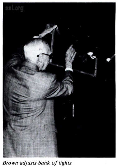
A VHS format video recording of William Brown’s wireless power beaming demonstration and the presentation of his paper is available for $25 including postage. The demonstration includes beaming power across the conference auditorium to both a bank of lights and the tethered helicopter.
*-will not appear in the proceedings.
LUNAR PROSPECTOR UPDATE

The Lunar Prospector program, headed by Principal Investigator, Dr. Alan Binder of Lockheed Martin, will build on the science of the Apollo program and return America to the Moon in June 1997.
The spacecraft and its launch vehicle, a Lockheed Launch Vehicle 2, are being built at the Sunnyvale facility and are being readied for launch in June, 1997. During a one-year polar orbiting mission Lunar Prospector will map the Moon’s surface composition, gravity and magnetic fields, and volatile release activity. These data are needed for expanding the lunar science legacy of Apollo, and for planning future exploration missions. Lunar Prospector will demonstrate that high quality science missions can be accomplished economically and within short time scales.
SCIENCE PAYLOAD
The Lunar Prospector science payload was chosen from a list of experiments proposed by NASA scientists for lunar mapping missions. The spacecraft carries six of the highest priority experiments, chosen for their scientific value, their ability to be flown on a simple, spin-stabilized spacecraft, and for their low mass, power and data rate requirements. The experiments are:
Gamma-Ray Spectrometer – The gamma-ray spectrometer is a more advanced system than was flown on the Apollo missions and will provide global maps of the elemental composition of the surface layer of the Moon. The main elements mapped are uranium, thorium, potassium, iron, titanium, oxygen, silicon, aluminum, magnesium and calcium. Knowledge of the concentrations qf these elements over the entire lunar surface will aid in understanding the composition and evolution of the lunar crust.
Though uranium, thorium and potassium are only trace elements, they are found concentrated in a material called KREEP (potassium [K], rare earth elements [REE] and phosphorus [P]). KREEP is not only the main source of these elements, but many other important trace elements such as zirconium, fluorine and chlorine. Mapping the locations and concentrations of KREEP deposits is important to lunar science as it is believed that the material developed late in the formation of the lunar crust and upper mantle, and thus can help define how the crust and mantle formed and evolved.
Neutron Spectrometer – While the Moon does not have any water of its own, theoretical calculations suggest that water brought to the Moon by comets and water-rich meteoroids may be frozen in the bottom of small craters in the polar regions. The floors of some small craters located within 30 degrees of the north and south poles never see sunlight and have continuous temperatures below -190 degrees centigrade. At such temperatures, water ice would be stable over the lifetime of the solar system. The neutron spectrometer on on Lunar Prospector has a water ice detectability limit of better than 0.01 % , which means it can locate 200 grams of water (a cup of water) in a cubic meter (about a cubic yard) of regolith (lunar soil). The discovery of lunar polar ice would have a profound effect on the economics and logistics of the exploration and colonization of the Moon and the inner solar system. It would mean that water, necessary for life support and as a source of both oxygen and hydrogen needed to produce rocket propellant, would be available in situ to future lunar explorers.
Alpha Particle Spectrometer – The alpha particle experiment is an advanced version of an experiment flown on Apollo 15 and 16. It will determine the locations and frequency of radon gas release events by detecting alpha particles from both radioactive radon gas and its decay product, polonium. This is the only orbital instrument which provides information on the current level of tectonic and volcanic out-gassing activity of the Moon. Thus, it provides unique information about the Moon which, until Apollo, was thought to be tectonically and volcanically dead. As a result of the Apollo surface seismometers and mass spectrometer and the orbiting alpha particle experiment, scientists now know that the Moon is active, though much less so than Earth.
Magnetometer and Electron Reflectometer – These two experiments map the lunar magnetic fields. While the Moon does not have a global magnetic field like the Earth, it does have weak fields of local extent. Mapping the strengths and distributions of these local fields over the Moon will determine if they were caused by an earlier global magnetic field like the Earth’s, if they were caused by meteroid impacts, or if they have some other origin. The data should also provide information on the size and composition of the lunar core and, coupled with Neutron Spectrometer data, could reveal correlations between magnetic fields and solar wind implanted hydrogen and helium concentrations.
On Earth, magnetic mapping is an important tool for locating economically important ore bodies. Similarly, the magnetic experiments will provide information to help understand the economic potentential of the Moon.
Doppler Gravity Experiment – This experiment provides the first complete gravity map of the Moon. Because no earlier mission was in a low polar orbit, NASA does not have an adequate lunar gravity model for planning follow-on unmanned and manned lunar missions. Lunar Prospector will define the lunar gravity field that affects the altitude, and thus the fuel quantity required for orbit maintenance of all orbiting spacecraft. It will also provide data on density differences in the crust, the internal density of the Moon, and the nature of the core.
THE SPACECRAFT
The Lunar Prospector spacecraft is a small, simple, reliable, spin stabilized spacecraft with a fully fueled mass of 233 kg (513 lb.). It is 1.42 m (4.6 ft) in diameter, 1.22 m (4.1 ft) in axial length drum with solar cells mounted on its outer surface which provide 202 watts of power. The scientific instruments are mounted on three booms to isolate them from the bus and simplify the spacecraftinstrument interfaces.
THE MISSION
The mission begins with launch in June of 1997. The flight to the Moon will take five days, during which two midcourse maneuvers occur, booms are deployed and science instruments begin to collect calibration data. Once the spacecraft reaches the Moon, it will perform three separate Lunar Orbit Insertion burns. The first bum will put the spacecraft into a 24-hour, elliptical orbit. One day later, the second burn will put the spacecraft into a four-hour elliptical orbit. Finally, 24-hours later, the third burn will insert the spacecraft into a circular, 118-minute, 100 km altitude, polar mapping orbit. At that point, the spacecraft will begin its nominal one-year mapping mission. During this phase, periodic orbital maintenance maneuvers will be made to keep the spacecraft in its proper orbit.
If, as expected, fuel is available at the end of the one-year nominal mission, the mapping will continue, first during a six-week phase in a circular, 50 km altitude orbit to obtain much more sensitive magnetic and gravity data and then from elliptical orbits as low as 10 km above the surface over a few areas of special interest. The mission will end when the fuel needed for orbital maintenance is depleted and the spacecraft impacts on the lunar surface.
HIGHLIGHTS IN THE HISTORY OF LUNAR PROSPECTOR
1985
SSI contracts James French of JPL to perform study to identify and characterize lowcost missions which could provide information concerning location and quantity of lunar resources. Particular focus to be given to polar regions to determine the presence of lunar ice.
Gerard O’Neill participates in National Commission on Space in forming recommendations to the President on the future direction of space exploration. He stresses that, among other goals, a robotic lunar orbiting prospector is essential.
1986
National Commission on Space publishes its report Pioneering the Space Frontier and includes a lunar probe as a priority. “It is a first priority to search the permanently shadowed craters near the lunar poles, where ice containing carbon, nitrogen, and hydrogen may be found.”
1987
O’Neill publishes article “Forward to the Moon” in which he urges a lunar polar probe be launched by the mid 1990s.
SSI initiates dialogue with JPL teams proposing “Lunar Getaway Special” and “Lunar Quicksat” missions as possible lunar orbiters.
SSI Senior Associate Ron Jones prepares high-resolution composite graphics to support SSI presentations.
SSI briefs NASA Administrator (James Fletcher) on two occasions about the lunar prospector concepts.
Dr. Fletcher is interested, and requests briefing from JPL on the “Lunar Quicksat.”
1988
SSI briefs members of Congress and requests Congress to authorize NASA to give SSI the use of a surplus gamma-ray spectrometer for the mission.
1989
SSI sponsors a Lunar Prospector Workshop in Princeton. Participants include: Binder, Carter, Canough and SSI.
Using the results of the workshop, Binder and Carter head a team to draft the Request for Proposals for a design study of the Lunar Prospector spacecraft.
SSI issues the RFP, and sponsors the design study.
The International Space University adopts the Lunar Prospector as their design project for the 1989 summer program. SSI Directors Burke and Maryniak and SSI Senior Associate Gay Canough chair the project session.
Omni Systems Inc. is selected as the design contractor.
Members of Congress formally request NASA to give SSI the use of a surplus Apollo gamma-ray spectrometer.
NASA Administrator Truly agrees in principal to SSI’s use of the surplus equipment, and appoints Dr. Alexander as liaison for the project.
1990
SSI contracts Omni Systems Inc. to design probe.
Representatives of NPO Energia visit SSI in Princeton, and talks initiate regarding the possible launch of the probe on a Soviet rocket.
A second Soviet delegation visits Princeton for meetings regarding a launch vehicle.
Omni Systems begins construction of a full-scale mock-up of the probe.
SSI and Lunar Exploration Inc. (LEI) form the Lunar Prospector Consortium in an effort to raise the $10 million needed for the mission.
Omni Systems completes the design study and a Critical Design Review meeting is held in California.
SSI representative meets with NPO Energia in Moscow, and a letter of intent regarding the launch is executed.
NASA and SSI sign the final agreement allowing SSI the use of the surplus Apollo instrument.
Yuri Semenov, head of NPO Energia, visits SSI in Princeton, and then travels to Houston to view the full-scale mock-up.
1991
Funding efforts continue, but SSI and LEI are unable to convince aerospace companies and other industry giants to donate to the program.
SSI and LEI brief NASA’s Space Exploration Initiative group (SEI).
SEI announces NASA sponsorship of four unmanned missions to the Moon
followed by two additional mappers and a single lander. LEI submits a $16 million proposal for the first mission.
SEI fails to fund any proposals.
1992
There are no prospects for funding Lunar Prospector despite growing interest in “faster, better, cheaper” missions as witnessed by the Clementine mission.
1994
LEI member Alan Binder submits a proposal on behalf of his employer, Lockheed Missiles and Space Company (LMSC) to NASA. The proposal to the new Discovery Program is to build and fly the Lunar Prospector.
1995
NASA chooses Lunar Prospector to go to the Moon in June of 1997 as a Discovery Project. Total program cost is $59 million. Alan
Binder of LMSC will be principal investigator.
Discovery Program survives NASA budget cuts.
DC-X UPDATE
One step backward for every two steps forward, that seems to be the way that the SSTO program is developing. After completing three flights in August and September of 1993, the program was shut down due to lack of funding. The ship and flight stand were mothballed in place at the White Sands Missile Range. There were serious concerns that the program might be zeroed out entirely in lieu of NASA SSTO efforts.
Finally, on May 3rd, just before McDonnell Douglas would have been forced to disband the DC-X flight team. BMDO received $3.5 million from ARPA to restart tests. Reconditioning of the DC-X took until June 11, 1994, when the engines were test fired.
On June 20, the DC-X lifted off the stand again. Following a more complex path than the three earlier flights, it ascended to 2,600 feet, traveled laterally 1,050 feet, reversed its direction and translated back towards the launch pad, climbing meanwhile to 2,850 feet, and then descended vertically, touching down after 2 minutes, 16 seconds. In a step forward over earlier flights, during which the rocket remained vertical throughout the flight, the angle of attack was varied from 0 to 70 degrees from vertical. This is in preparation for the rotation maneuver from nose-first to hover, which must take place during an actual SSTO return from orbit, and which the DC-X is intended to demonstrate.
On June 27 disaster struck. Seventeen seconds into the second flight after refurbishment hydrogen, routinely vented from the tanks before launch, was ignited by air-purge duct fans, ironically intended to disperse the vapors and keep them from accumulating under the craft. The resulting explosion tore a 4 by 15-foot hole in the aeroshell and slightly cracked the liquid hydrogen tank. Surprisingly, even though the explosion occurred during liftoff, the DC-X took off normally and began its preprogrammed flight. Seventeen seconds into the flight, the ground crew noticed pieces of the shell falling off and activated the craft’s emergency “autoland” procedure. “This anomaly resulted in successful demonstrations of several important firsts: executing the autoland sequence demonstrating an ‘aircraftlike abort’ mode; landing on the gypsum [instead of the concrete landing pad], demonstrating the ability to land future SSTO vehicles virtually anywhere; and demonstrating the system’s toughness and robustness, since the DC-X continued to fly despite the aeroshell damage” (Lt. Col. Jess Sponable, Single Stage Rocket Technology program manager for the Ballistic Missile Defense Organization).
The DC-X was subsequently returned to Huntington Beach for repairs and a new aeroshell has been fabricated by Scaled Composites of Mohave, CA. Unfortunately, repairs have heated up the rest of the money allocated for the flight tests, so McDonnell Douglas is currently awaiting additional funding.
Following completion of the DC-X flight tests, the program will be transitioned from ARPA management to NASA. McDonnell Douglas will return the vehicle to the factory and upgrade it into the DC-XA. Improvements will include: a new graphite epoxy liquid hydrogen tank, a LOX tank made from a new Russian aluminum-lithium alloy, a new graphite epoxy intertank structure, and a gaseous oxygen-hydrogen reaction control system.
NASA is now the major player in the SSTO game. Recently, NASA released a Cooperative Agreement Notice requesting proposals for the X-33 Reusable Launch Vehicle (RLV) Advanced Technology Demonstrator. The X-33, the formal name for the proposed craft that SSTO advocates were previously calling the SX-2, will “demonstrate critical elements of a future Single-Stage-To-Orbit (SSTO) rocket power RLV (Reusable Launch Vehicle). The X-33 will be an integrated systems testbed for advanced launch technologies applicable to a next generation RLV.” Three major teams have expressed intentions to respond. McDonnell Douglas and Boeing are teaming up; their proposal will probably be a variation on the Delta Clipper, the full-scale Vertical Take-off Vertical Landing (VTVL) craft following the DC-X design. Lockheed is also entering the race with a Vertical-Takeoff Horizontal Landing (VTHL) lifting body featuring a linear aerospike engine. Finally Rockwell is proposing a winged cylindrical VTHL craft derived from Shuttle technology.
THIN FILM DISC SHAPED LARGE SPACE STRUCTURES
– SUNSAT OR SOLAR SAIL
A PROPOSED CONSTRUCTION/ASSEMBLY METHOD
Eric M. Flint
Institute for Structural Mechanics
DLR
Braunschweig, Germany
This paper is intended to start a discussion on feasible design strategies for a recently proposed solar power satellite (SPS). This SPS is unique in that it takes advantage of advances in solar collecting technology to reduce the total mass of the array, hence the support structure as well.
One proposed configuration, called the “bicycle wheel,” will be studied here in detail. It is assumed that the first such SPS will be assembled in low-Earth orbit and then boosted to its operational geosynchronous orbit. Given this, a telerobotic assembly of terrestrial fabricated parts is proposed. The SPS consists of a central mast from which prefabricated thin film array wedges are robotically deployed from their rolled-up configuration. The exact number of required rolled-up wedges depends on launcher geometrical constraints. The tubes about which the arrays are rolled form a higher stiffness rim for the array structure as it is deployed. Guy wires and rotationally induced forces will be used to provide further stability. During assembly it is envisaged that a similarly designed “construction base” with long spars instead of arrays will provide some added stability and mounting locations for the assembly robots. It should also be possible to use the same construction method to build thin film disc-shaped solar sails.
1.0 Introduction
Recent developments in solar energy collecting technology make it possible to consider solar arrays directly deposited on thin, lightweight films. It has also been proposed to deposit the required microwave transmission electronics on the thin film as well, thus reducing power transmission losses. The primary attraction of such Thin Film Arrays (TFA) is that they are lightweight. This in turn leads to the possibility of lighter support structures.
One proposal (Landis and Cull, 1991) that takes advantage of the combination of thin film technology and the resulting lightweight structural support is shown in Fig. 1.1. For obvious reasons, it is typically referred to as the Bicycle Wheel Design. The heart of the proposed satellite is a thin film with solar collecting arrays on one side and microwave transmitting equipment on the other. Thus, during parts of the SPS orbit, it is possible to collect energy on one side and beam it directly to Earth from the other.
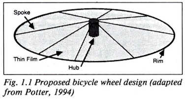
The critical TFA is supported by a rim that runs about the entire circumference. Additional rigidity is provided by the so-called spokes, which are actually guy wires because they carry tension only. A stiff inner hub or mast provides the anchoring point for the TFA and the guy wires. It additionally provides structural support for other required systems such as guidance and control, batteries (for the occasional eclipse, communication and attitude control.
Preliminary studies (Potter, 1994) have shown that such a satellite with slightly over 1 Km radius could deliver from GEO orbit to Earth (35° latitude) 5 gigawatts of power with a peak beam intensity of 30 mW/cm2. These are the typically accepted requirements that an SPS must satisfy in order to be competitive with other possible power sources.
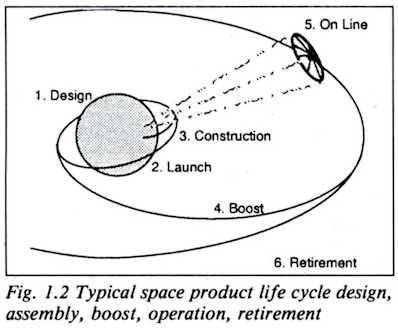
With the basic feasibility of the concept established, there remain many issues that must be considered. The major topics of concern can be divided into 6 categories; the design phase itself, how to launch it, how (and where) to construct it, how to get it to the proper operational orbit, its performance requirements while “on-line,” and finally what to do with it once the end of its usefulness has been reached. While each of these stages (shown in Fig. 1.2) is important to the overall design, it is critical to consider how the structure will be build (step 3) as early as possible.
It is for this reason that a method of constructing the proposed Bicycle Wheel Design is presented in this paper. As with all new ideas, the first concern (after it is shown to be feasible from a scientific viewpoint) is to deade if it can be realized. If not, then further design studies about how nice it would be (if it could be built) are pointless. As this paper shows, there does exist at least one potential construction method, so the first hurdle has been passed.
During the development of this construction process some of the extensive literature for SPS construction was reviewed (Nansen & DiRamio, 1978, for example). Unfortunately, most of these ideas are based on the assumption of planar solar arrays requiring large structural support structures. Large deployable antennas have long been a subject of study (Rogers et al., 1990), and while it is also possible to garner some ideas from this field, there is a critical difference in the design goals. For antennas, surface accuracy is critical leading to a need for stiff support structures. However, the deployment ideas for solar sails (Friedman, 1988) do bear further study and provided much of the inspiration of the work presented here.
The first section of the rest of this paper is an executive overview of the proposed construction method. The exact, step-by-step construction sequence is presented next, and is followed by a more detailed review of the various components of the thin film satellite and construction base. It is here that various equations are provided to help aid subsequent studies for smaller or larger designs. The use of these equations is then illustrated for two cases.
The first case is a 100 m radius array that could serve as a technology demonstrator version of the final one km radius array that is studied next. The final sections review some of the remaining issues that must be considered before it can be said that the thin film disk design is feasible and provide a summary.
2.0 Executive Overview
It is envisaged that, at least initially until the technology is proven, the disc shaped thin film satellites will be assembled in low-Earth orbit from material fabricated into their near final form on Earth. The final assembly could be achieved with robots that function autonomously or under the supervision of telepresenced human operators.
The satellite itself will be anchored to a construction base during assembly. This base serves as a rigid (compared to the disk shaped satellite) foundation on which to support the required construction robots and store materials until needed. At first, the disc satellite will consist of a single central mast. To this rings to support the guy wires and thin film array are attached. The thin film itself is fabricated on Earth where the required reflective, solar array or microwave transmission equipment is deposited. In a track provided for later repair and inspection robots, the needed guy wires are stowed. The array is stored in a rolled up form, much like aluminum foil, but with the critical difference that is shaped like a wedge.
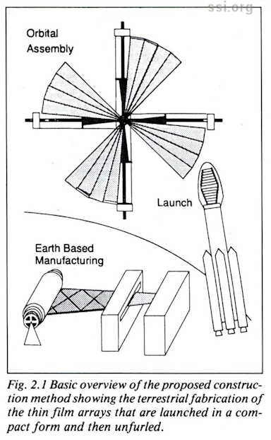
This compact form is launched into orbit. As each wedge contains all the required elements for its assembly, a single launch failure does not critically halt the assembly process. Having each wedge identical to each other eases the bookkeeping required, simplifies design and allows an assembly line type manufacturing to be employed resulting in further cost savings. The essentials of this process, terrestrial-based manufacturing into a compact form that is then launched to orbit and unfurled is illustrated in Figure 2.1.
3.0 Construction Plan
In this section a detailed, step-by-step description of the envisaged construction process is given. Note that no dimensions are given as this construction method can be scaled depending on the final desired radius of the disc satellite. Also the critical dimensions of wedge length and stowed radius depend on the choice of launchers.
3.1 Terrestrial Manufacturing
Shown in Figure 3.1 is a schematic representing one possible way to fabricate the thin film. The first step is the extrusion, or weaving, of the base thin film material. This film is then drawn through the next machine where solar arrays and microwave transmitters (or reflective surfaces) are deposited depending on the end use of the disc satellite. This machine also integrates the robot inspection tracks and guy wires along each side.
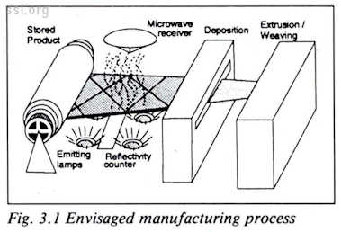
Before the resulting product is rolled up onto the rim piece (probably made of lightweight composite) it is radiated with simulated solar light. The resulting transmitted microwave power or reflected light is used to check the quality of the deposited surface. As the fabrication proceeds, the area made is tapered down so that the end product, when unfurled, is a wedge. This process is highly repetitive and can be realized in a production line manner as each wedge should be identical. This leads to the economies of scale.
3.2 Launch
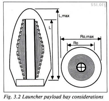
As the construction of each wedge is completed it can be suitably protected and transported to the launch site where it is integrated into the launcher. The choice of the particular launcher is immaterial (assuming it can loft the mass of the stowed wedge) to this method except for the critical dimensions of the payload area length and maximum stowable radius (see Fig 3.2). As shown later, the maximum length determines the number of wedges needed. The payload radius determines the maximum disc satellite radius it can support, but this does not appear to be critical.
As each stowed wedge contains all the material needed for its deployment, the unfortunate loss of any one launch does not hinder the construction process. This, along with the fact that each wedge is identical, ensures that there are no critical fabrication bottlenecks to prevent the material from reaching orbit as needed and adds robustness and simplicity to the overall process.
3.4 Disc Satellite Assembly Sequence
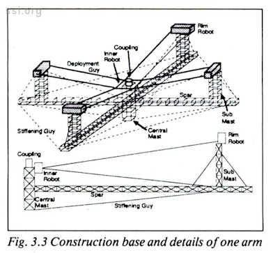
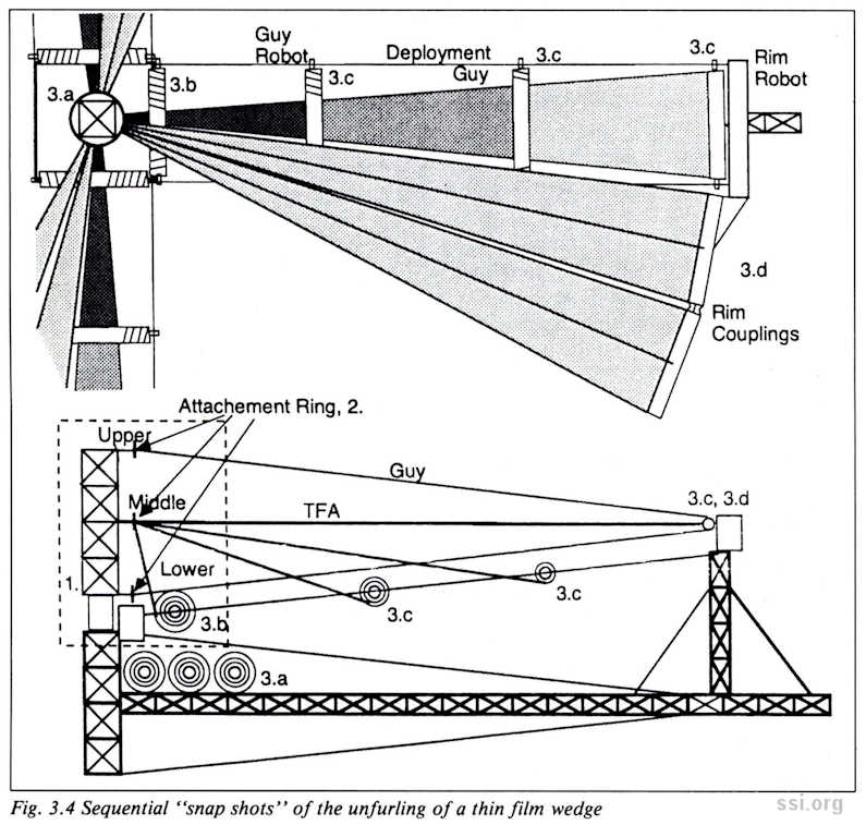
Once the construction base is in place, the disc satellite can be assembled. The exact steps are given in Table 3.1, and most are detailed in Figure 3.4. First, the central mast of the disc satellite is attached to the construction base (step 1). This is followed by the attachment of mounting rings at the top, middle and bottom of the mast to hold the upper guy, thin film array root and lower guy (step 1).
With this complete, the next step. is to move the rolled TFA wedge from its storage position to the deployment area using the stevedore robots (step 3a). The protective coverings are removed while the rim piece is mounted between the deployment guys that stretch from the inner robot to the rim robot. The wedge is then unfurled slightly by the mast robot until the wedge root is attached to the central ring. The mast robot then continues “upward” until the upper guy is secured. The lower guy is secured at the same time. This (step 3b) situation is shown by the area enclosed with a dashed box.
The wedge is then moved along the deployment guys toward the rim robot (step 3c). This movement is assisted by the rotation of the construction base and is controlled by the guy robots. As the thin film deploys, the constraints on guy wires caused by the lower layers are released, and the guy wire basically “falls” out. This process continues until the wedge is fully unfurled and the rim robot latches on the rim, and the guy robots are released to return to the inner robot to start the next deployment process.
| Table 3.1 Construction Schedule | |
|---|---|
| 1 | Deployment of central mast |
| 2 | Attachment of mounting rings |
| 3 | Unfurl thin film array a. Move wedge from storage b. Attach wedge and upper and lower guys c. Roll out wedges d. Attach rim to its neighbors, attach guys e. Check out wedges (add to power net) f. Rotate partially completed disc satellite so next wedge can be deployed g. Repeat until done |
| 4 | Separate construction base |
| 5 | Attach “despun” unit, top off propellant tanks |
| 6 | Spin Up, lock out rim, boost for orbit |
At the rim robot, the available ends of the guy wires are unlocked and moved to the center of the rim on which they are mounted. The rim robot additionally deploys the latching devices to attach the currently “active” rim to previously deployed rims. The entire disc satellite structure is then rotated relative to the construction base by the angle of a single wedge and resecured. The rim is allowed to slip too, so that at the end of the rotation maneuver, the rim robot “holds” only one end of the previously active rim.
This maneuver is needed to clear the way for the deployment of the next wedge which is being secured into place at the inner robot, while the rotation takes place. When the rotation is complete, the unfurling process repeats itself until all the wedges are deployed and the outer rims are all locked together. This process occurs simultaneously on each deployment axis. Multiple axis assembly is used to decrease the total construction time and maintain satellite symmetry during construction, which simplifies the attitude control task.
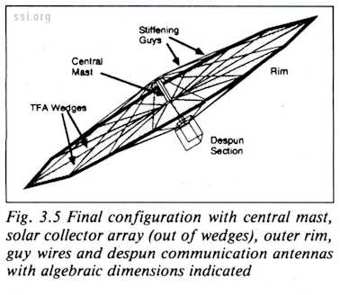
Once the final wedge has been deployed and its rim locked into place, the now essentially complete disc satellite is released from the construction base. A despun section for attitude control and communication (similar to that of the construction base) is put into place. The propellant tanks are topped off, and the rotation rate of the disc satellite is increased to its operational rate, and the satellite is then transferred to its operational orbit. The final form of the disc satellite is shown in Figure 3.5.
The resulting increased outward radial forces due to the new rotation rate serve to further pre-stress the guys and membrane and also lock out the attachment devices between the rim pieces that were previously flexible. This need to spin up the satellite after construction is the primary reason each wedge is not connected to its neighbor. If they had been, high stresses could be generated at the connection points requiring a stronger (and thus heavier or more complex) design.
4.0 COMPONENT DETAILS
4.1 Thin Film Collector Arrays
The thin film forms the heart of the whole disc satellite. On it the collecting array components, reflective surfaces or microwave power transmitting elements are deposited as needed. It includes the electrical interconnects to distribute power from the collectors to the transmitters or central hub, deal with shadowinduced shorting (probably using diodes) and dissipate excessive heat on the shadowed side. Additionally, it must include methods to deal with the electrical charging that will occur.
Reinforcements, called rips, to halt the growth of tears caused by inevitable micro meteorite and space junk impacts are essential. While in operation, a method of accessing all parts of the thin film to inspect for damage and make repairs must also be provided. To make things even more difficult, the thin film must be amenable to the proposed deployment method.
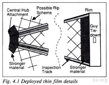
In Figure 4.1 the general shape of the deployed wedge is seen with the inspection and repair robot track at the edge. Stronger material is used at the points where the thin film is attached to the central mast and the outer rim in order to ensure better force transfer and reliability. The shown hatched rip scheme is complementary with the stowage technique by ensuring a constant average thickness. Also indicated is a very thin film protective sheet between each layer. This serves to prevent the elements of one layer from damaging the elements of another level while stowed. This film can either be removed during deployment (as indicated in the picture) or serve as an ablative to help protect the array from energetic oxygen atom impacts while in the low-Earth assembly orbit.

Figure 4.2 shows a partially deployed thin wedge and a more detailed cross section of the overlapping of the stowed thin film. Note how the wedge shape provides room on one side of the film to create an added thickness or raised elements at the edges of the film. This capability is used to place the repair track. Due to the overlapping, anything stored in the repair track will be locked into place until that layer is pulled free during the deployment process. This property is used to store the guy wires.
As detailed back in Figure 3.2, R and L are limited by the launcher payload bay geometry. If the desired satellite radius, R, is known, the required number of stowed layers to achieve this can be calculated by iteratively increasing the number of layers, nl, until the desired radius is reached (and probably exceed a little) from

which can be simplified to

This expression results from treating each stowed layer as a circle with the resulting total length (i.e., satellite radius) being the summation of the circumferences. The inner radius ri, is determined by the maximum radius of curvature of the thin film material can tolerate.
With the number of required layers known, it is then possible to solve for the outer radius of a stowed array wedge as

This allows one to select a feasible launcher. Typically the needed ro is much smaller than the available launcher radius. This allows the possibility of lofting multiple wedges in one launch. Generally, a hexagonal storage pattern seems to optimize the quantity to orbit.
The length dimension of the stowage rim can be sized to fit the desired launcher as needed with one exception. The choice of L must result in an integer, N, that is divisible with no remainders by the number of construction axes used. This requires another iterative solution using the fact that the angle of each wedge can be calculated as

where R is taken from Eq. (4.1) and L is the length of each rim piece. From this it is easy to determine the number of required wedges

if alpha was calculated in degrees. This iterative process will probably result in an L slightly lower than the payload capability.
The total ideal surface area is simply the sum of the area of each wedge (which are equilateral triangles)

This area will be slightly larger than the area calculated if a circle of radius R is assumed because the rim is not a circle but rather an approximation to a circle formed by straight lines. The amount of the discrepancy decreases as the number of wedges increases. The increased area is desirable though because it helps to partially compensate for the loss in area caused by the central mast, repair track, rips, and higher strength connections at the rim and mast.
4.2 Rims
The rim section shown in Figure 4.3 performs several functions. First, it provides a convenient method of storing the thin film while it is being manufactured and launched. The rim also carries most of the launch loads and provides a convenient connection point for transportation. Its hollow interior gives a low mass and provides additional storage area. Upon deployment they are already connected to the thin film (removing one construction step) and provide a convenient rigid place to mount the guy wires. The spring lock system provides flexibility during assembly and helps relax tolerance requirements. After the completion of the disc satellite and spin up to operational speeds, the now locked rim spring system adds rigidity to the structure, helps distribute point loads around the structure, and helps prevent the satellite from collapsing in on itself if rotation is lost.
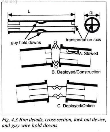
Especially important is the operation of the spring-lock system. During assembly (Figure 4.3.b) it is desired that there be flexibility between each rim section to simplify the assembly. However, once completed (Figure 4.3.c), the rim should be as rigid as possible. As the satellite spills up to operational speed the distance between each rim will increase. This will eventually overcome the spring stiffness, allowing the fixture to take its locked-out form. Until needed, these spring-lock systems are stored inside the hollow rim section (Figure 4.3.a).
Also critical are the design of the force transfer mechanisms to the thin film and the guy tie downs. They are recessed in order to not interfere with the storage of the thin film. A transportation deployment axis is provided at either end of the rim section but does not seal it completely.
The radius, Ri, noted in Figure 4.3 is determined by the maximum radius of curvature of thin film. The inner radius is determined by the loads the rim section must carry. This radius might increase to allow room for the recessed force transfer points. The remaining empty space could possibly be used to store propulsion fuel to use with attitude or spin control rockets that could be recessed and integrated into the rim section design. It could also serve as a shielded area for power redistribution conduits and local power transmission efficiency monitoring equipment.
4.3 Guys
Guys are necessary in order to add stiffness to the whole structure and ensure that the array does not vibrate excessively out of plane. The required set of top and bottom guys for each wedge rim are stored in the repair tracks along the edge of the stowed wedge. As the wedge unrolls the guys naturally “fall out as the constraining neighbor layer is removed” as shown in Figure 4.2.
The total amount that can be stored in this manner is limited to

To accommodate for the added length needed to reach from the tip of the mast (instead of the center) to the rim, the guys are wrapped around the stowed array in the last stage of manufacturing. The total length needed can be calculated from a simple application of Pythagoras’s theorem

where H is the height of the central mast. At the end of the wedge deployment process the rim robot detaches the end of the guy wires from the inspection track and moves them to the middle of the rim to be attached to the guy wire tie downs. As a final note, these guys must be very reliable. If one breaks it could snap around, foul other guys, or impact and damage the thin film array (perhaps catastrophically).
4.4 Central Mast
The central mast is primarily used as a point to connect the thin film array. It has height in order to create some out of plane forces in the TFA through the guy wires. It also serves as a convenient spot to place central computers, store propellant and batteries to support the satellite during eclipses and provides an interface for the despun section. Most likely it will be of a truss construction to achieve desired stiffness for a low mass.
4.5 Despun Unit
For some of the standard systems of a space satellite, the design becomes easier if they do not spin with the rest of the spacecraft. Specifically this includes the communication and attitude control. It is envisaged that Sun pointing of the array will be achieved using thruster firing. Design is simplified if the overall axis of the structure is defined from a non-rotating basis. Design requirements are relaxed further if the thrusters can be fired continuously as needed. On a rotating section the analysis and required control of the pulse firing becomes more complicated.
While batteries can be placed anywhere in the system, their specific design depends on the number and depth of discharges. As the SPS is designed for GEO orbit, and the construction base supplies power during the assembly, it makes sense to incorporate the batteries towards the end of the assembly. This leads towards incorporation in the despun section which is integrated last.
4.6 Assembly Robots
A critical part of the assembly process is the manipulators using to move and position the parts. It is assumed that the robots will operate with human telepresence guidance. The use of astronauts might be simpler, but would greatly complicate the design due to the necessary greater safety considerations.
The deployment process depends on the inner, mast, guy, and rim robots as explained in Section 3.4. Stevedore robots move the stowed wedge from its storage place to the inner robot prior to unfurling as needed. Smaller, general purpose robots might be needed to fix the main robots, fix tears in the TFA, clear jams and, in general, provide a mobile set of eyes and hands for the telerobotic operators. Tracks to facilitate their movement about the thin film arrays are provided at the edge of each wedge.
5.0 Case Studies
In this section, two examples are looked at to help illustrate the issues inherent in Equations 4.1-4.6. In these examples, several values were assumed. Most notably, it was assumed that a large launcher (like the Titan IV or Space Shuttle) would be dedicated to delivering the stowed wedges to the construction orbit. Hence the maximum length was restricted to under 15 m. Similarly the maximum radius is limited to 2.2 m.
Two cases for rim radius and TFA thickness were considered. The first, pessimistic, case assumes that large rims are needed, and that each layer is a factor of 10 thinner, and that the TFA can be bent to a tighter curvature by a factor of two, as reported in table 5.1.
——————————
Table 5 .1 Assumed Parameters
| Payload Bay (Titan IV, Shuttle is slightly larger) | ||
|---|---|---|
| Lmax | 15m | |
| Rmax | 2.2 | |
| Pessimistic | Hopeful | |
| TFA thickness t | 1mm | 0.1mm |
| rin inner radius ri | 0.5m | 0.25m |
It should be noted that while large launchers were used in these case studies, there are several practical limits to their use. First, in kg to orbit, they are generally more expensive than the newer, smaller classes. Second, they are mostly optimized for delivering cargo to GEO. The large rockets are also booked to capacity with large backlogs, so counting on their use is problematic at best. Finally, in the advent of a launch accident, proportionally greater resources are lost in a large launcher.
This, however, might be balanced by added risks and complexity if multiple smaller launches are used. For example, smaller wedges require more assembly, an increased number of dockings, etc, that increases time and risk of the construction stage. Smaller rockets, however, do boast a greater frequency to orbit, lower unit costs, lower costs per disaster, etc.
As the case studies show, the limiting factor is the available payload length. On the other hand, the available radius allows multiple stowed wedges in one launch. As a tradeoff, one might use a longer than normal payload bay with reduced radius, thus decreasing the number of wedges, but increasing the number of needed launches.
5.1 100 M Technology Demonstrator
The first case study concentrates on a small prototype version of the final SPS. Such a prototype is easier to conceptualize, has a lower initial cost, allows demonstration of the feasibility of manufacturing, launching and assembly schemes, and there is a smaller possibility of severe structural dynamic issues.
The results of these studies are shown in Table 5.2. Obviously the length of each wedge should be as long as possible in order to minimize the number of required wedges. Being limited to 15 m by the payload size leads to 44 wedges or 11 wedges per quarter. Due to slight variations in the resulting disk radius between the pessimistic and hopeful case (caused by different number of layers required to achieve the nominal radius) slightly different rim lengths are needed.
The major difference between cases is the stowed outer radius, and hence, how many stowed array wedges can fit (using a hexagonal arrangement) inside the payload radius. For the pessimistic case, only 19 wedges will fit requiring 2+ launches. The smaller radius hopeful case allows 61 wedges and can be lofted in one launch.
5.2 1 KM “On-line” SPS
Once the techniques have been proven, it would be possible to begin construction of the full scale SPS. Using the standard assumptions, pessimistically one will need 60 Titan IV launches to place the required thin film array wedges into orbit. More hopefully, the other case only requires a little over 11 launches.
——————————
Table 5.2 100 m Radius Disk Satellite Results
Nominal radius 100 m
Number of wedges, N 44
| Pessimistic | Hopeful | |
|---|---|---|
| number or layer, nl | 31 | 63 |
| disk radius R | 100.51 m | 100.23 m |
| rim length, L | 14.375 m | 14.336 m |
| wedge outer radius, ro | 0.531 m | 0.2563 m |
| # bundles/launch | 100.51 m | 100.23 m |
| #Launches | 2.315 | 0.72 |
| Pessimistic | Hopeful | |
|---|---|---|
| number or layer, nl | 254 | 572 |
| disk radius R | 1001.4 m | 1001.5 m |
| rim length, L | 14.981 m | 14.982 m |
| rim outer radius, ro | 0.754 m | 0.3072 m |
| # bundles/launch | 7 (2.26 m r) | 37 (2.15 m r) |
| #Launches | 60 | 11.35 |
6.0 OTHER POTENTIAL USES
The primary purpose of the technology demonstrator would be to demonstrate that power can be collected in space and delivered to Earth. It would additionally serve to validate the construction techniques and suggest areas for improvement. Upon completion of test objective, it could then be used to supply additional power to the space station, goo-synchronous communication satellites or other possible customers who are outside of the attenuating atmosphere. Smaller transmitting distances also would allow small transmitting antennas and higher pointing accuracy. Additionally, as the disk satellite would normally be pointed directly at the Sun, it could be used as a permanent base for mounting Sun observation telescopes. The central mast could also be mounted with experiments to study the long-term effects to materials exposed to the geosynchronous orbit. These other “customers” would give added value to the project and help insure the successful completion of the first stage, clearing the way to begin work on the full scale collector.
7.0 SOME REMAINING ISSUES
A wide range of issues remain to be addressed before a decision to proceed with more detailed design studies can be made. First, the exact constellation of receiving and transmitting satellites must be resolved (mirror, tether or other). Additionally, other technologies and configurations for supporting the thin film collectors should be considered.
In order to form accurate weight estimates, it is critical to know the size of the various components. This, in turn, is driven by the needed safety factors and load definitions for the launch, construction, boost to orbit, and on-line service portions of the SPS life. The susceptibility of the design to damage and the potential risks of damage due to orbital debris and micro meteorites need to be addressed. This is critically dependent on the orientation in construction orbit as influenced by gravity gradients and how the supplies will be delivered.
Additionally, issues of thermally induced oscillations and the entire realm of structural dynamics must be reviewed. The latter could prove of great importance with regard to load levels and fatigue. It must be shown that it is possible to achieve the attitude control requirements without exciting structural modes. This is also influenced by the choice of the rotational speeds needed to keep the array from collapsing in on itself.
Last and most important, the design must be searched for single path failure modes, and the probability of their occurrence must be made very small or redundancy added.
8.0 SUMMARY
In this paper, a possible construction method for the proposed bicycle wheel space power satellite has been presented. While still at the preliminary conceptual level, it shows that there is a feasible method available. Considering how to construct the satellite during the initial steps of the design helps ensure that a reasonable final design is reached. The method proposed should also be directly applicable to solar sails.
The construction method is implicitly understood to occur in low-Earth orbit and guided by humans through telerobotic links. However, once the initial technology is proven, there should be no difficulty in performing the assembly work elsewhere. One possible exception to this (in the near term) is the manufacturing and rolling into the stowed form of the thin film array.
As the final size of the structure is still an open question, equations were presented in symbolic form that should allow quick parameter calculations in latter design iterations. Using these equations, case studies were performed for a proposed 100 m radius technology demonstrator and a 1 KM radius “on line” SPS.
Nomenclature
| A | total cross sectional area of disk satellite |
| H | height of central mast |
| L | rim length |
| N | number of required wedges |
| R | radius of disk satellite |
| nl | number of layers needed to reach desired disk satellite radius |
| lg | length of stiffening guy wire |
| ri | radius of rim |
| ro | outer radius of stowed thin film array |
| a | angle of circle covered by each wedge |
Acknowledgements
The author would like to thank the staff of the Space Studies Institute for providing the chance to begin such interesting research.
References
Friedman, L., 1988, Starsailing, John Wiley & Sons, New York.
Landis, G., Cull, R., 1991, “Integrated Solar Power Satellites: An Approach to Low-Mass Space Power,” Proceedings of SPS ’91: Power from Space Conference, Paris/Gif-sur-Yvette, France, 27-30 August, pp. 225-232.
Mallove, E., Matloff, G., 1989, Star Flight Handbook, John Wiley & Sons, New York.
Nanse, R., Ramio, H., 1978, “Structures for Solar Power Satellites,” Journal for Aeronautics and Astronautics, October, pp. 55-59.
Potter, S., 1994, “Low Mass Solar Power Satellites Built from Lunar or Terrestrial Materials: Final Report,” Space Studies Institute, Princeton, NJ.
Rogers, C., Stutzman, W., Campbell T., Hedgepeth, J., 1990, “Technology Assessment and Development of Large Deployable Antennas,” 41st International Astronautical Congress, Dresden, Germany, October.
ITEMS FOR SALE
BOOKS
The High Frontier by Gerard K. O’Neill $ 9.95
Technology Edge by Gerard K. O’Neill 9.95
Space Manufacturing 9, (Proceedings of the May 1993 Conference) 59.95
Space Manufacturing 10, (Proceedings of the May 1995 Conference 40.00
The Threat of Large Earth-Orbit Crossing Asteroids (Hearing before the Subcommittee on Space of the Committee on Science, Space, and Technology, US House of Representatives, March 24, 1993) 25.00
MIR I Space Station: A Technical Overview 79.00
YOUNG PEOPLES
Bibliography 2.00
Mass-Driver Instruction Kit 2.50
AUDIO/VISUAL PACKAGES
Living in Space: Space Stations & Colonies (35 mm annotated slide set) 35.00
Opening the High Frontier 35.00 Mass Driver (20 slide set with description) 20.00
New Harvest (VHS tape of slide show) 25.00
The Vision (VHS tape of G.K. O’Neill interview) 25.00
The Vision (audio tape of interview) 8.00
The Solar System’s Greatest Resource (audio tape of John S. Lewis’ banquet address) 10.00
Wireless Power Beaming (VHS tape of William C. Brown’s demonstration) 25.00
PAPERS
Solar Power Satellite Design With Thin Film, Seth Potter, author 10.00
NASA: Lunar Enterprise, Case Study Task Force (1990) 25.00
Composites, Brandt Goldsworthy, author 3.00
First Steps to Lunar Manufacturing, Results of the 1988 SSI Lunar Study 10.00
The Low (Profile) Road to Space Manufacturing, Gerard K. O’Neill, et al. 2.00
Mass Driver III, Les Snively and Gerard O’Neill, authors 3.00
New Routes to Manufacturing in Space, Gerard K. O’Neill, et al. 2.00
Orbital Transfer Vehicles, Chris Buja, author 2.00
Report on Space Shuttle External Tank Applications, Alex Gimarc, author 12.00
Self-Replicating Machines for Space, Gregg Maryniak, author 2.00
Solar Power Satellite Built of Lunar Materials, Space Research Associates 11.00
OTHER
Newsletter, SSI Update back issues 3.50
Bibliographies: Standard 4.00 / Young People’s 2.00
Special Research Report (25 copies) 6.25
SSI Sticker 1.00
To order, circle items and mail your order to SSI, PO Box 82, Princeton, NJ 08542.
[[librarian note: This address is here, as it was in the original printed newsletter, for historical reasons. It is no longer the physical address of SSI. For contributions, please see this page]]
———————-
ABOUT THE INSTITUTE
The Space Studies Institute is a nonprofit, international, research and educational organization. Founded in 1977, it is dedicated to opening the High Frontier of space.
SSI’s goals include using the material wealth and solar energy of space to improve the human condition both for those who live on Earth and those who live in space, and to build Earth-like habitats in space to expand the ecological range of humanity throughout the solar system and ultimately, perhaps, throughout the galaxy.
To this end, SSI has conducted and is conducting pioneering research into advanced space propulsion, the extraction and processing of nonterrestrial materials for engineering purposes, and the identification and location of lunar and asteroidal resources.
Following are four opportunities for participation in SSI activities:
Corporate Membership
SSI’s Corporate Membership program offers access to SSI’s broad base of technical advisors, access to a resume pool, and access to exhibit space at the biennial SSI Conference on Space Manufacturing. Research partnerships are encouraged.
Senior Associate Program
The Senior Associates Program is currently SSI’s largest source of funds for High Frontier research and education. The program also provides a way for anyone interested in the High Frontier to play a key role in making space colonization and space manufacturing achievable within our lifetimes. Following is a description of the program.
The Senior Associate program was created in 1979 to generate the steady funds that SSI needs to conduct research projects, most of which require money for several years. Today we have about 1,000 active Senior Associates; 537 Senior Associates are on their second, third, or fourth pledge. The program provides about 60% of SSI’s annual budget and is essential to both our research and educational activities.
Senior Associates receive special benefits as our thanks for their support. These benefits include invitations to special events, free mailings of publications by SSI, NASA, and other space organizations; and confidential newsletters, describing SSI developments before they are made public.
However, most people become Senior Associates because they want to see space colonization become a reality; they give muchneeded funds and join the group of people working to create the High Frontier in our lifetimes. As Senior Associates, they also meet others who share their enthusiasm for space exploration and development. Each Senior Associate makes a five-year pledge to SSI, choosing one of the ranks below:
Associate: $100.00 annually
Fellow: $200.00 annually
Colleague: $300.00 annually
Distinguished Colleague: $500.00 annually
Payments can be made annually, semiannually, quarterly, or monthly.
Each Senior Associate receives a number with his or her rank, indicating when he or she joined the program. For example, the next person to join could become Fellow 368, or Distinguished Colleague 126. Each Senior Associate receives a certificate, signed by SSI’s president, as a permanent record that he or she was one of the first people who gave critical support to the High Frontier. The names of the Senior Associates will also be permanently maintained by SSI to provide historians with the names of early High Frontier supporters.
Regular Membership
SSI Membership is open to individuals worldwide. All members receive the lnstitute’s newsletter, which is published bimonthly and keeps all SSI members abreast of SSI research, an SSI membership card and decal. Membership fee: Regular $25.00; Senior Citizen or Student $15.00; non-US addresses, please add $10.00.For gifts of $50.00 or more, you will receive an SSI lapel pin.
With gifts of $100.00 or more, you will receive a copy of Dr. O’Neill’s book, The High Frontier.
Volunteer Program
As a nonprofit organization, SSI relies on the expertise of many volunteers worldwide to assist in the areas of research, education, presentations, development of visual arts, and technical writing.
If you are interested in the future in space, contact SSI by letter, phone, FAX, or E-mail.
Board of Directors
Dr. Roger O’Neill, Chairman
Prof. Freeman Dyson, President
Dr. Joseph P. Allen
Mr. James Burke
Dr. George Friedman
Mr. Morris Hornik
Mr. Gregg Maryniak
Dr. Fred Rose
Dr. Lee Valentine
Board of Governing Members
Mr. James Burke
Prof. Freeman Dyson
Mr. W. Brandt Goldsworthy
Ms. Bettie Greber, Executive Director
Mr. James Laramie
Mr. Gregg Maryniak
Ms. Tasha O’Neill
Dr. David Odom
Dr. Fred Rose
Dr. Lee Valentine
Mr. David Wine
Board of Senior Advisors
Col. J. Paul Barringer
Barringer Crater Company
Mr. Richard Boudreault
Technologies Aerospatiales
Dr. William C. Brown
Raytheon, retired
Mr. Christopher J. Faranetta
NPO Energia, Ltd.
Mr. George Gallup, Jr.
Gallup International
Mr. Richard E. Gertsch
Colorado School of Mines
Mr. Alex Gimarc
Anchorage, Alaska
Dr. Peter Glaser
A.D. Little
Mr. James Harford
AIAA
Ms. Kathy Keeton
OMNI Magazine
Mr. Jeffrey Manber
NPO Energia, Ltd.
Dr. Rashmi Mayur
United Nations
Mr. Burt Rutan
Scaled Composites, Inc.
Mr. Steven Vetter
Minneapolis, MN
ABOUT THE NEXT ISSUE …
Seeds in Space:
The final findings of SSI’s current research project with USC exploring and evaluating the key enabling technologies which will most robustly fulfill the High Frontier mission will be included in the October/November/December 1995 issue of SSI Update.
Commercial Space Transportation
by Walter Kistler, Bob Citron and Thomas Taylor will be featured. This article will describe the design, construction, testing, and operational plans the Kistler Aerospace Corporation has for a fleet of fully reusable rocketships.
©space studies institute
NEXT: Oct-Nov-Dec 1995 SSI Research, O’Neill article, ARPA VR Surgery
