
SPACE STUDIES INSTITUTE
P.O. BOX 82
PRINCETON, NEW JERSEY 08542
[[librarian note: This address is here, as it was in the original printed newsletter, for historical reasons. It is no longer the physical address of SSI. For contributions, please see this page]]
THE HIGH FRONTIER® NEWSLETTER
VOLUME XX ISSUE 1 JANUARY/FEBRUARY 1994
FROM THE EXECUTIVE DIRECTOR
In This Issue
This issue of SSI Update includes the latest report from Dr. Seth Potter on SSI’s research project updating the design of a solar power satellite using a thin-film design. Dr. Potter is finalizing his report at this time, but reports to us that, based on his work so far, an overall reduction of mass of more than 60% is feasible. These exciting results are likely to bring SPS once again to the world’s attention as an energy alternative.
The second article, Clementine: An Experiment to Flight Qualify Lightweight Space Technologies, details the spacecraft and mission dedicated to Gerard K. O’Neill. Further updates and data on Clementine’s mission will be included in future issues of SSI Update.

On page 5 there is general information on the Institute as well as its membership programs. We hope you will share this information with a friend.
Independent Research Opportunities
SSI is pleased to announce the opportunity for independent research projects. We have begun compiling a list of important research projects that can be undertaken on a volunteer basis by researchers or graduate students. The current available areas of study include: asteroids, comet cores, space colony design, mass-drivers and propulsion. SSI will offer a project outline, objectives, direction, contacts (where possible), and a review process for qualified people to conduct short-term projects. Following the review process there will be opportunity for publication of the results.
If you are interested in receiving more information, please send your resume to us along with a letter describing your area of interest. We will also be making this opportunity available to those outside the SSI community on the internet computer network, but will give preference to all SSI Senior Associates and Members. This is an excellent opportunity for you to become directly involved in SSI’s research plan for 1994.
Outreach Program
The SSI volunteer speakers’ bureau has handled many requests over the past two months and has received much press coverage. If you are interested in becoming an SSI spokesperson or would like to arrange for a presentation in your area, please contact the SSI office.
SSI Membership
The annual SSI Membership and Renewal drive is now underway. Please take a moment to renew your membership. Your support is critical to SSI’s success. We would also like to thank all of you who sent in recommendations for prospective members. The campaign has been very successful. If you have not yet sent in recommendations, please send the names and addresses to Barbara Faughnan. c/o SSI, P.O. Box 82, Princeton, NJ 08542. We will promptly send them membership information.
Because of the poor service we were receiving from our E-mail carrier, we are now in the process of switching companies. Unfortunately as we go to press, the new number is “in the mail.” By the time you get this newsletter, we should be up and running with our new number. Don’t hesitate to give our office a call to get the new number!
Included in the member renewal mailing is a new brochure for the SSI credit card with MBNA. This program has proved to be a very good source of extra research funds and is steadily growing. If you haven’t already done so, we urge you to help us out by signing up. SSI receives a small but well received bonus each time a member signs up, upgrades his card and/or makes a purchase using the card. The bonus to SSI is not based on a percentage of your bill, but on the number of purchases. (Make many small charges!) Senior Associates did not receive this brochure, but we’ll be happy to send you one if you let us know.
Thank you again for your support. With your help we intend to make 1994 SSI’s most successful year.
Bettie Greber
LOW MASS SOLAR POWER SATELLITES BUILT FROM TERRESTRIAL OR LUNAR MATERIALS
By Seth D. Potter
One of the major constraints on the eventual deployment of solar power satellites (SPS) is the cost of launching large amounts of material into space. Two research strategies have been pursued in order to circumvent this problem. One approach, supported by SSI for many years, is to build the SPS out of nonterrestrial (particularly lunar) material. The March/April 1993 issue of Update contained an excerpt from Dr. Gerard K. O’Neill’s book, Technology Edge: Opportunities for America in World Competition, in which he points out that launching a given amount of material from the Moon to high orbit takes less than a twentieth as much energy as launching the same amount of material from the Earth. When other factors, such as atmospheric resistance on the Earth, are accounted for, the savings in launch costs from the Moon versus the Earth may amount to a factor of fifty. In 1985, Space Research Associates completed an SSI-commissioned study, in which the NASA/ Department of Energy reference SPS was redesigned to take full advantage of lunar resources. It was shown that approximately 99% of an SPS can consist of lunar materials. The 8% increase in overall mass compared to an SPS built from terrestrial materials was considered to be a relatively small price to pay for this advantage.
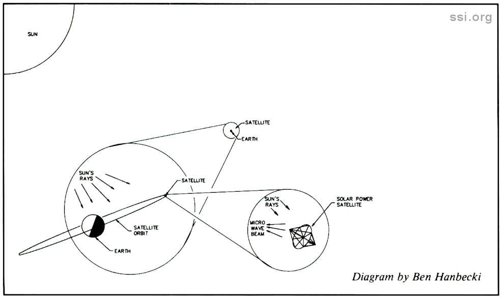
The SPS designs mentioned above have masses of about 50,000 metric tons and generate 5 GW (gigawatts, or thousands of megawatts) of electricity. Recently, therefore, another strategy for reducing SPS launch costs has been considered. Work at the NASA Lewis Research Center has shown that it may be possible to use thin-film solar cells deposited on a lightweight substrate along with solid state microwave transmitters. Since the entire area of the substrate can be covered with microwave transmitters as well as solar cells, large effective transmitting antenna diameters become feasible. Due to the physics of power beaming, the larger the transmitting antenna, the less the microwave power beam will spread as it reaches the Earth. Since the rectifying antenna (rectenna) at the Earth’s surface can now be made correspondingly smaller, the SPS need not supply as much power as a conventional SPS in order to be economical. (Indeed, it ought not to supply as much power, or else the microwave beam will become too intense.With smaller SPS’s having a lower mass per kilowatt of power generated, the system becomes easier to build and finance.
Current research at New York University, supported by SSI, aims to achieve the best of both approaches to launch cost reduction by using thin films and lightweight substrates built from lunar materials. The first step in the study was to consider two lightweight SPS designs suggested by Geoffrey Landis and Ronald Cull of the NASA Lewis Research Center: the “bicycle wheel” and the “inflatable sphere.”
The bicycle wheel SPS would consist of a diskshaped solar cell/transmitter array stretched out over spokes, with a pole running through its center. Additional stiffness would be provided by guy wires running from the ends of the pole to the rim of the array. Since the array cannot directly face the Earth and the Sun simultaneously, there will typically be about a 30% loss in power. This can be made up for by using a mirror that orbits along with the SPS. The mirror would track the Sun and reflect light to the SPS, which would face the rectenna site on the Earth. Although this would increase the available power, and, perhaps more importantly, assure a more constant supply of power, the mirror would weigh about as much as the SPS, thereby increasing the total mass required to supply a given amount of power by about 40%. In the inflatable sphere concept, the solar cell/transmitter array would be a giant balloon supported by a low-pressure gas. The mass of this gas would be quite small compared to that of the array. However, some of this advantage may be lost due to the fact that the array itself has four times as much actual area as crosssectional area (due to the fact that the surface area of a sphere is four times its cross-sectional area). It would thus have four times the mass of the equivalent bicycle wheel array, not counting the support structure of the latter.
In order to design a lightweight SPS, it must be kept in mind that if the entire array area serves as both solar collector and a microwave transmitter, then as the array is increased in size, more power is being collected and squeezed into a tighter beam. Thus, a limit on beam intensity will set a limit on the size of the SPS. In this study, a peak beam intensity of 30 milliwatts per square centimeter was assumed (the intensity near the edge of the beam is, of course, much lower). This is the same as in the Space Research Associates study mentioned earlier, and is not significantly different from the NASA/DoE figure of 23 milliwatts per square centimeter. It is also only three times the US safety standard for human exposure to microwaves. Thus, as seen in other SPS studies, the microwave power beam is no death ray.
Another important parameter to consider is the frequency of the power beam. For a given transmitting antenna size, the higher the frequency, the narrower and more intense the beam. Thus, for high frequencies, the array must be kept small in order to avoid too concentrated a beam. For lower frequencies, a larger array is needed in order to keep the beam from spreading out too much as well as to supply enough power to make economical use of the land area at the rectenna site.
NASA researchers have investigated several different thin-film photovoltaic materials, such as cadmium sulfide (CdS), copper sulfide (Cu2S), copper indium diselenide (CuInSe2), and amorphous silicon (a-Si). The latter compares favorably with the other materials in terms of the efficiency at which it converts solar energy into electricity. All of these materials are radiation-tolerant, thereby eliminating the need for a protective cover glass. They are also low in mass, and therefore, inexpensive for the quantities that will be needed. Amorphous silicon is at a slight disadvantage in terms of light degradation (10 to 15% after two years, compared to, say, CulnSe2, which has none), but it is believed that this can be improved upon. Because of its favorable characteristics, and the fact that it is the only thin-film photovoltaic material available on the Moon, amorphous silicon served as the basis for this study for both the terrestrial and lunar SPS. An efficiency of 11.5% was used, based on NASA projections of achievable efficiencies for the 1990’s. The material considered for the substrate for an SPS built of terrestrial materials was Kapton polyimide. This is the same material used to make rectenna substrates. Steel foil was the substrate of choice for an SPS built of lunar materials. The thicknesses considered were based on NASA figures for advanced substrates, and were 7.5 microns for Kapton and 7.5 microns for steel foil.
A bicycle wheel SPS using thin-film technology will have a diameter of just over 4 kilometers for a power beam frequency of 2.45 gigahertz (this is the frequency of the NASA/DoE reference design). It will supply about 450 megawatts of power to consumers. The mass of the solar cell/transmitter array (including the substrate, but not the support structure) is just over 200 metric tons if Kapton is used for the substrate (terrestrial materials), and just under 800 tons if steel foil is used (lunar materials). The effect of increasing the frequency was also considered. A 10GHz power beam yields a bicycle wheel SPS that has half the diameter, and thus one-fourth of the array mass and power level as the 2.45 GHz design; i.e., roughly 2km, 50 tons (terrestrial) or 190 tons (lunar), and 110 MW. A bicycle wheel with a mirror, or an inflatable sphere will be 8.5% smaller in diameter and supply 19% more power than a conventional bicycle wheel, due to the elimination of the tracking loss. Higher frequencies will yield even smaller, more easily constructed SPS’s, but the amount of power for their size will be lower, since higher frequencies are subject to rain and air attenuation, and solid state microwave transmitters are less efficient at higher frequencies.
Preliminary research in the design of the support structures indicates that they can be built from lightweight materials available both on the Earth and on the Moon. A likely terrestrial material is a graphite organic matrix. A likely lunar material is a glass/glass laminate. Both materials are light in weight, with the graphite organic matrix being somewhat lighter. These two materials have opposite coefficients of thermal expansion. They can be combined to yield a material with zero coefficient of thermal expansion. Only a small amount of glass needs to be added to the graphite to achieve this, making this a feasible approach for a terrestrial SPS, but not for a lunar SPS, since graphite is not available on the Moon. Thus, a lunar SPS supported by a glass/glass laminate structure may have a problem with thermal expansion. However, the design of the support structure is presently in its early stage, so it is not yet known if this is a serious problem.
Dr. Peter Glaser, the originator of the SPS concept, has called for a “terraced” approach to SPS technology development. In this approach, smaller projects would pave the way toward a full-scale geostationary SPS. One possible small or mid-sized project would be an SPS in low Earth orbit beaming power to a rectenna near the equator for a small portion of each orbit. (One such project is the Japanese SPS 2000 program.) Using thin-film technology, an SPS in low Earth orbit may be light enough to be launched by a single Space Shuttle mission. For a bicycle wheel SPS orbiting at an altitude of 1200 kilometers, beaming power at a frequency of 10 GHz, the diameter would be 340 meters, the power available to consumers would be 3 MW, and the array mass would be an amazingly low 1430 kilograms (though the support structure would increase the mass). The full capacity of such an SPS can be exploited if a series of SPS’s and equatorial rectennas are spaced such as to enable a given rectenna to lock onto the next SPS after the previous one has disappeared from view. The previous SPS would then lock onto another rectenna, further east.
If support structures can be redesigned which weigh about as much as a photovoltaic array built from terrestrial materials, then overall specific power levels of about 800 to 1000 watts per kilogram may be possible for a terrestrial SPS. Since the NASA/DoE reference SPS had a specific power level of about 100 watts per kilogram, the potential improvement is considerable. In addition to the improvement in specific power, a thin-film SPS would be smaller in overall size than the NASA/DoE reference design; thus making each SPS a more easily financed step in the growth of a national or international power system. A thin-film SPS built from lunar materials would lose some (but not all) of the specific power advantage; however, the lowering of launch costs may make this worthwhile, if a lunar infrastructure can be constructed and operated economically.
To date, thin-film solar cells have been produced in relatively small moqules at maufacturing volumes far below that required for SPS construction. The substrates commonly used are not lightweight. Research in depositing thin film solar cells on lightweight substrates is only just beginning. However, the promise of thin-film technology, combined with future world energy needs, suggests that it worthwhile to develop manufacturing technologies which would allow thin-film solar cells to be deposited on lightweight substrates and produced in large quantities.
CLEMENTINE: AN EXPERIMENT TO FLIGHT QUALIFY LIGHTWEIGHT SPACE TECHNOLOGIES
By Col. Pedro L. Ruston, Mission Manager
Abstract
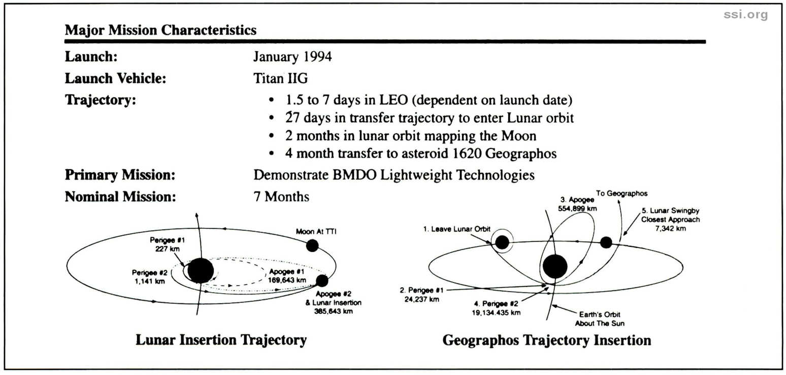
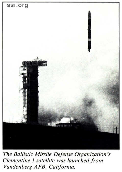
The Clementine spacecraft which was dedicated to noted space pioneer, Gerard K. O’Neill, was launched January 25, 1994 aboard an Air Force Titan IIG rocket at 11:34 EST. Using a very lean management style, the program developed the spacecraft, built by the Naval Research Laboratory in less than two years. The spacecraft has a dry mass ofabout 235 kg, made possible by using very lightweight components. The sensor suite consists of two star tracker cameras, an ultravioletvisible camera, a short wave infrared camera, a long wave infrared camera, and a lidar, weighing less than 7kg and covering the wavelength range from 0.3 to 9.5 microns. Additional novel, lightweight technologies (inertial measurement units, reaction wheels, batteries, computers, and microelectronic solid-state recorders) have also been incorporated in the basic system design. The mission plan called for a solid rocket motor, configured as the third stage ofa Titan IIG booster, to propel the spacecraft from a low-Earth orbit to a Moon-Earth orbit. The vehicle will assume a polar orbit around the Moon on February 20, 1994. Following an approximately two month imaging period, the spacecraft will then execute a flyby of the near-Earth-asteroid 1620 Geographos. In the process, it will flight qualify many advanced lightweight technologies and enable the transfer of these technologies to the civilian scientific sector.
Introduction
In September 1990, NASA Administrator Richard Truly inquired of Deputy Secretary of Defense Donald Atwood as to the possibility of utilizing the advanced, lightweight technologies being developed for the Ballistic Missile Defense Organization (then known as the Strategic Defense Initiative Organization) in a joint space exploration mission. After a six-month study effort by NASA, DoD, and industry, it was concluded that a mission to a near-Earth-asteroid was desirable and feasible from both organizations’ standpoint. The mission was subsequently expanded by two months to include a mapping of the Moon to demonstrate sensor performance prior to the demanding asteroid flyby. On a humorous but practical note, the name Clementine was selected for the spacecraft because the old ballad “Clementine” describes the excavation of a mine and this mission would assist in determining the mineral content of the Moon and the asteroid. Additionally, as in the song, after the asteroid flyby, Clementine will be “lost and gone forever.”
Overall Space Characteristics
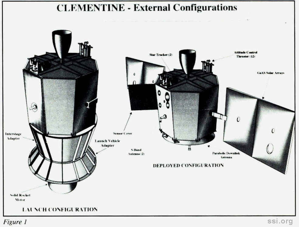
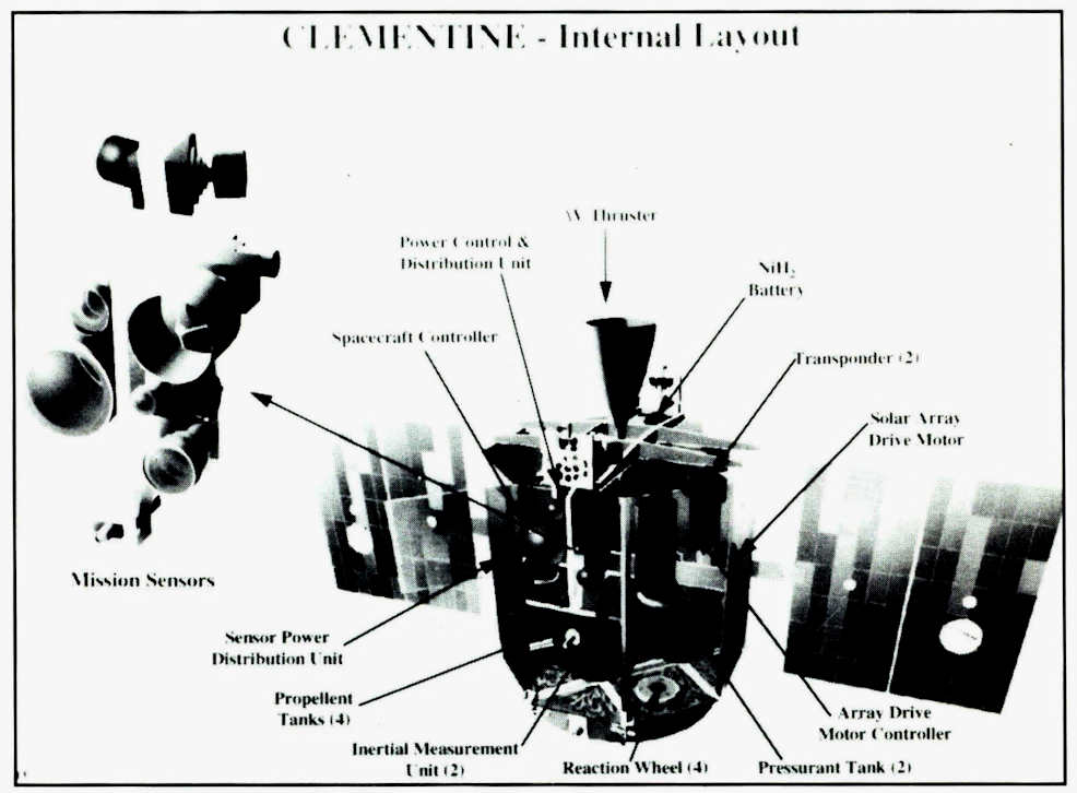
The total mass of the spacecraft in the launch configuration is 1690 kg, with most of the weight in the solid rocket motor required for lunar insertion. The Spacecraft dry mass is 235 kg and fuel is 223 kg (Figure 1). The spacecraft propulsion system consists of a monopropellant hydrazine system for attitude control and a bipropellant nitrogen tetroxide and monomethyl hydrazine system for propulsive maneuvers. The bipropellant system has a total capability of about 1.8 km/s with about 550 m/s required for lunar insertion and 540 m/s for lunar departure. The remaining propellant is used for error correction, lunar orbit maintenance, and asteroid flyby. During initial deployment at low-Earth-orbit (LEO), the spacecraft is 3-axis stabilized. Then the spacecraft is spun up and the kick motor fired. After motor jettison, the spacecraft is 3-axis stabilized via reaction wheels providing a stabilization of 0.05°. The attitude control system includes two inertial measurement units based on a ring laser gyro and an interferometric fiber optic gyro.
Spacecraft data processing is performed by two computers. A 16-bit radiation hardened computer with a capacity of 1.7 million instructions per second is used for safemode, attitude control system, and houskeeping operations. A reduced instruction set computer (RISC) 32-bit processor with 18 million instructions per second is used for image processing and autonomous operations. During imaging operations, the data are stored in a 2 Gbit dynamic solid state recorder and later transferred to the gound stations using a 128 kb/s downlink. The spacecraft is commanded from the ground using a 1 kb/s uplink from the NASA Deep Space Network and the DoD stations. The power system consists of a gimbaled, single axis, GaAs/Ge solar array providing a total spacecraft power of 360 watts at 30Vdc. The solar array is used to charge a 15 A-h NiH2 common pressure vessel battery.
Spacecraft Orbits
The spacecraft was launched from the Air Force Western Test Range, Vandenberg AFB, into a 260 x 300 km parking orbit at a 67° inclination. After a few days in LEO, the solid rocket motor boosted the spacecraft into a phasing orbit transfer trajectory to the Moon. The spacecraft will be trapped in a 425 km x 2940 km, 5 hour orbit around the Moon for about 10 weeks. The mission timeline was designed to flyby the near-Earth-asteroid Geographos on 31 August 1994[1].
Advanced Lightweight Spacecraft Technologies
The Clementine spacecraft will flight qualify several of the most advanced lightweight technologies ever developed in a cost effective and stressing operation space test. The spacecraft design deviates from the normal practice of using military standard components and, instead, introduces commercial plastic parts which are not hermetically sealed. All commercial plastic parts were pre-screened and traced to ensure quality assurance. The spacecraft subsystems were designed to operate in the mission space environment for a full year. Several of the technologies incorporated into the lightweight sensor suite and into the major spacecraft subsystems are discussed below. As will be apparent, this is the first space test of such advanced systems.
Light Sensor Suite
Star Tracker Camera (STC). The Clementine STC weighs 370g and has an accuracy of 100 to 300 µrad. The camera performs a 3-axis attitude determination with only one starfield image. The wide field of view of the camera, 29° by 43°, is designed to minimize the star catalog by using the brightest stars. The focal plane array is a silicon charged couple device (CCD) operating between 0.4 and 1.1µm with a pixel format of 384 x 576 and a pixel size of 23 x 23µm. The present design has an aperture of 14.4 mm and a focal length of 17.7mm, operating at a very fast f/1.28. The STC electronics operates at a maximum frame rate of 10z with 8 bits in the analog/digital converter.
UV/Visible Camera (UVVC). The Clementine UVVC weighs 500g and is designed for inexpensive manufacture and calibration. The optics, filter wheel, and camera assembly are modular. The focal plane array consists of a phosphor overcoated silicon CCD for UV and visible response between .3 and 1.1µm. The pixel format is 384 x 288 and the pixel size is 23 x 23 µm. Expected resolution from lunar orbit is 100 m/pixel, and at Geographos, is 30 m/pixel. The optics consists of a catadioptric Si02 glass with an aperture of 46 mm and a speed of f/1.96. The imaging has a field of view of 4.2° x 5.6°. The UVVC electronics operate at a maximum frame rate of 30 Hz with 8 bits in the analog/digital converter. The NASA science team selected filter wavelengths for this camera to permit mineralogical mapping of the Moon and Geographos. For the UVVC, these filters are centered at 0.415, 0.75, 0.90, 0.95, and 1.0 µm.
Lidar High Resolution Camera. The 1250g high-resolution camera (HRC) consists of an intensified S20 photocathode silicon CCD which operates between 0.4 and 0.8 µm with a pixel format of 384 x 288 and a pixel size of 23 x 23 µm. Expected resolution from lunar orbit is 30 m, and at Geographos, is 5 m. The optics consists of a shared Cassegrain telescope with reimaging lens and beam splitter, an aperture of 13.1 cm, and a speed of only f/9.5. An imaging field of view of 0.4 x 0.3 degrees is used to obtain the high resolution in the camera design. The filter wavelengths selected by the science team were 0.415, 0.56, 0.65, and 0.75 µm. A fifth filter was selected as broadband over the wavelength range from 0.4 to 0.8 µm.
Lidar Laser Transmitter. With a mass of 1000g and a size of about 4 x 10 x 22 cm, the laser transmitter is a highly portable device with many applications in the commercial and military sector. The laser is a Nd:YAG diode pumped laser operated a 1.064 µm. The pulse energy is 180 millijoules with a 10 ns pulse length. This laser transmitter can be operated continuously at 1 Hz or in bursts at a higher repetition rate. With the present power design and thermal management, the laser can be operated for 400 pulses at 10 Hz. For Clementine, this instrument will provide ranging data from which topographical information on the lunar surface may be derived.
Short Wave Infrared Camera (SW/RC). The SWIRC is a compact imager designed to detect and track in the IR range. It has a mass of 1600 g. The focal plane array is a 256 x 256 photovoltaic InSb array. The optics are catadioptric with a 2 cm aperture and a speed of f/5. The SWIRC field of view is 5.6° x 5.6°. The filter wavelengths selected by the science team were 1.1, 1.25, 1.50, 2.0, 2.6, and 2.78 µm. The camera electronics operate at a frame rate of 10 Hz. An active sterling cycle cryocooler is integrated with the camera to maintain the focal plane array below 77° K.
Long Wave Infrared Camera (LWIRC). At 1650 g, the LWIRC camera is quite compact and is extremely valuable in investigating cold objects against a space background. The focal plane array is a 128 x 128 photovoltaic HgCdTe array with a pixel size of 50 x 50 microns. The optics type is a Cassegrain-Reig at an aperture of 150 mm and a speed of f/2.3. The array field of view is one degree by one degree and operates without filter wheel to image from 8 to 9.5 µm. The electronics operate at a repetition rate of 30 Hz. An active Sterling cycle cryocooler is built as part of the LWIRC to extract over 0.25 watts from the focal plane maintaining a temperature of 65° K.
Advanced Spacecraft Subsystems
Lightweight Spacecraft Subsystems. The electric power system, the attitude control system, and the computer processing system were also designed to incorporate advanced lightweight components. Most of these components were developed by the DoD to be used in ballistic missile defense applications where weight reduction is essential to system integration. Since the spacecraft weight is directly related to the launch cost, these technologies are of great value to the commercial and civil space sectors. The use of these technologies in the Clementine spacecraft should encourage their use in many commercial applications.
Electrical Power System (EPS). Two advanced technologies were introduced in the EPS, a common pressure vessel (CPV) nickel hydrogen battery and a 5.5 mil thick gallium arsenide on germanium solar cell. Even though nickel hydrogen batteries have been flown as an independent pressure vessel (IPV) since 1976[2], the more compact, higher energy per kilogram common pressure vessel nickel hydrogen battery has not been flown previously. The NiH2 CPV battery offers twice the power and one-half the mass of IPV batteries. The 9.5 kg, 15 Amp-hour, Clementine spacecraft battery design uses a unique containment and fin system to provide 47.1 watthour/kg, which is about 8% more than previously flown NiH2 IPV batteries[3]. Additionally, the incorporation of a 5.5 mil gallium arsenide on germanium with a 301 watt/m2 is the thinnest GaAs/Ge solar cell yet flown.
Attitude Control System (ACS). Two advanced lightweight technologies are also incorporated in the ACS. The Clementine spacecraft incorporates the two lightest inertial measurement units (IMU) developed by the Ballistic Missile Defense Organization, a 500 g ring laser gyro and a 650 g interferometric fiber optic gyro. These IMUs incorporate lightweight packaging and applications specific integrated circuits for a 2:1 weight reduction over existing IMUs. These units are radiation hardened to about 10 kRads (Si) and contain no devices subject to destructive latchup. Both units have a drift rate of about 1°/hr and operate at a power of 10 W. Four lightweight reaction wheels are also incorporated in the spacecraft ACS. The drive electronics of these reaction wheels are integrated with the wheel assembly to provide increased reliability and about 30% weight reduction. The Clementine reaction wheels have a mass of 2 kg, use about 10 W total, and are designed for a three year mission.
Computer Processing System (CPS). In addition to a radiation hardened 16-bit processor which is used for standard spacecraft housekeeping operations, Clementine uses a 32-bit RISC processor for the image data from the sensor suite. This is the first application of 32-bit RISC processor architecture in a spacecraft. The Clementine 32-bit processor is a R3081 RISC processor with 18 MIPS and 3.5 MFLOPS which is radiation hardened to near 20 kRads (Si) and has no latchup components. During standard mapping operations, the CPS stores the data in a solid state data recorder (SSDR) with a total storage of 2 Gbits. This SSDR is four times larger than any previously flight qualified solid state recorder. The SSDR has been designed for high reliability by using redundancy error detection and correction with active fault management and built-in-test. The SSDR has a data throughput greater than 20 Mb/s with a bit error rate less than one bit per 10 billion. The weight of the SSDR is 3.4 kg, uses a maximum of 15 W, and consists of commercially available 4 Mb dynamic random access memory systems. A compression chip developed for future space exploration missions would provide various image compression options.
Conclusion
The Clementine spacecraft will be the first time the DoD performs a deep space mission. The use of celestial bodies such as the Moon and a near-Earth-asteroid are ideal targets to flight qualify advanced lightweight technologies. The added cost of the mission by going to deep space is actually less than the cost of developing and deploying the targets that would be required to test the payload in LEO. Since Clementine is an engineering mission, extensive diagnostics have been used to test the advanced systems in the sensor suite and in the subsystems. By performing a joint mission with NASA and forming a NASA-selected science team to enhance the scientific value of the mission, it will also be possible to transfer these technologies for future space exploration, bringing true meaning to the term “dual use.”
But Clementine is more than a joint DoD/NASA program to flight qualify advanced technologies; the program also implements a lean management style to make space missions faster and cheaper than ever before. From the beginning of the Clementine program, there was a clear intent to avoid the huge infrastructure and managerial style that drives spacecraft costs to hundreds of millions of dollars and stretches program durations to many years. For example, the program cost and schedule were set at the beginning of the program and they were monitored monthly to ensure full compliance. The total program duration, from mission go-ahead to launch, was fixed at two years (the program was actually completed in 22 months!) and the total spacecraft cost (including launch vehicle) at 75 million dollars. It is hoped that the innovative technologies and the management techniques in the mission be considered in the future to significantly reduce costs and schedule without compromising the scientific and engineering yield.
Acknowledgements
The author wishes to thank Paul Regeon and his staff at the Naval Center for Space Technology in the Naval Research Laboratory for their outstanding performance integrating the Clementine spacecraft. The author is also indebted to Lyn Pleasance and his group at the University of California Lawrence Livermore National Laboratory for their superb effort designing and manufacturing all the sensors used in the Clementine spacecraft.
References
1. Nozette, S., and E. Shoemaker, “Back to the Moon, on to an Asteroid: The Clementine Mission,” The Planetary Report, pp. 10-15, Sept/Oct 1993.
2. Betz, Fred, “The NTS-2 Nickel Hydrogen Battery,” NASA Publication 2041, Paper Presented at the 1977 NASA Battery Workshop, June 23, 1977.
3. Baker, W.E., Garner, J.C., and D.J. Short, “The DSPSE Spacecraft Electrical Power System, “IEEEC Paper 93214, 28th IEEEC Proceedings, Atlanta GA, August, 8-13, 1993.
This article is an excerpt from an article printed by EOS.
ABOUT THE INSTITUTE
The Space Studies Institute is a nonprofit, international, research and educational organization. Founded in 1977, it is dedicated to opening The High Frontier of space.
SSI’s goals include using the material wealth and solar energy of space to improve the human condition both for those who live on Earth and those who live in space, and building Earth-like habitats in space to expand the ecological range of humanity throughout the solar system and ultimately, perhaps, throughout the galaxy.
To this end, SSI has conducted and is conducting pioneering research into advanced space propulsion, the extraction and processing of nonterrestrial materials for engineering purposes, and the identification and location of lunar and asteroidal resources.
Following are four opportunities for participation in SSI activities:
Corporate Membership
SSI’s Corporate Membership program offers access to SSI’s broad base of technical advisors, access to a resume pool, and access to exhibit space at the biennial SSI Conference on Space Manufacturing Research partnerships.
Senior Associate Program
The Senior Associates Program is currently SSI’s largest source of funds for High Frontier® research and education. The program also provides a way for anyone interested in the High Frontier to play a key role in making space colonization and space manufacturing achievable within our lifetimes.
Following is a description of the program.
The Senior Associate program was created in 1979 to generate the steady funds that SSI needs to conduct research projects, most of which require money for several years. Today we have about 1,000 active Senior Associates; 537 Senior Associates are on their second, third, or fourth pledge. The program provides about 60% of SSI’s annual budget and is essential to both our research and educational activities.
Senior Associates receive special benefits as our thanks for their support. These benefits include invitations to special events, free mailings of publications by SSI, NASA, and other space organizations; and confidential newsletters, describing SSI developments before they are made public.
However, most people become Senior Associates because they want to see space colonization become a reality; they give much needed funds and join the group of people working to create the High Frontier in our lifetimes. As Senior Associates, they also meet others who share their enthusiasm for space exploration and development. Each Senior Associate makes a five-year pledge to SSI, choosing one of the ranks below:
Associate: $100.00 annually
Fellow: $200.00 annually
Colleague: $300.00 annually
Distinguished Colleague: $500.00 annually
Payments can be made annually, semiannually, quarterly, or monthly.
Each Senior Associate receives a number with his or her rank, indicating when he or she joined the program. For example, the next person to join could become Fellow 368, or Distinguished Colleague 126. Each Senior Associate receives a certificate, signed by SSI’s president, as a permanent record that he or she was one of the first people who gave critical support to the High Frontier. The names of the Senior Associates will also be permanently maintained by SSI to provide historians with the names of early High Frontier supporters.
Regular Membership
SSI Membership is open to individuals worldwide. All members receive the Institute’s newsletter, which is published bimonthly and keeps all SSI members abreast of SSI research, an SSI membership card and decal. Membership fee: Regular $25.00; Senior Citizen or Student $15.00; non-US addresses, please add $10.00.
For gifts of $50.00 or more, you will receive an SSI lapel pin.
With gifts of $100.00 or more, you will receive a copy of Dr. O’Neill’s book, The High Frontier.
Volunteer Program
As a nonprofit organization, SSI relies on the expertise of many volunteers worldwide to assist in the areas of research, education, presentations, development of visual arts, and technical writing.
If you are interested in the future in space, contact SSI by letter, phone, e-mail or FAX:
Space Studies Institute
P.O. Box 82
Princeton, NJ 08542.
E-mail: call the office for our new email
[[librarian note: This address is here, as it was in the original printed newsletter, for historical reasons. It is no longer the physical address of SSI. For contributions, please see this page]]
©space studies institute
