SPACE STUDIES INSTITUTE
P.O. BOX 82
PRINCETON, NEW JERSEY 08542
[[librarian note: This address is here, as it was in the original printed newsletter, for historical reasons. It is no longer the physical address of SSI. For contributions, please see this page]]
SSI UPDATE
THE HIGH FRONTIER® NEWSLETTER
VOLUME XVII ISSUE 2 MARCH/APRIL 1991
VICE PRESIDENT’S COLUMN
Aluminum Mine in Orbit
For the past year, SSI has been working with a ‘tiger team’ from the Air Force Institute of Technology on a project to salvage aluminum from Space Shuttle External Tanks in Earth orbit. This issue of Update includes excerpts from the team’s 390 page Master’s degree thesis. (Copies of the full report will be available from SSI. Please contact us for price and availability.)
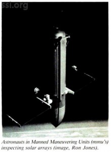
This project was made possible by the contributions of the Senior Associates and Members of SSI and by a contract from the Martin Marietta Corporation. We are very grateful for this support. Senior Associate Ron Jones produced the photo montage images used to illustrate the article on this project. A paper on this project will be presented at the upcoming SSI Conference on Space Manufacturing by one of the team members.
An Invitation
SSI members have a unique opportunity to learn about and participate in the Institute’s work. Every two years SSI conducts the Conference on Space Manufacturing at Princeton University. These conferences have been at the very forefront of advanced space exploration and industrialization for almost 17 years. In addition to providing a chance for leaders in the field to communicate with one another, they give our members a chance to learn first hand about our work .
Back in my Chicago days, I led several expeditions to the Princeton Conferences with members of the Chicago Society for Space Studies. A dozen of us would make the pilgrimage to meet with people like Gerard O’Neill, Peter Glaser, Bill Brown and other leaders in space research. Before our first trip, some of our team wondered if they would be able to understand the technical presentations, while some of the engineers wondered if they would be bored by the political and economic sessions.
What we discovered was that each of us came away with a much broader understanding of the overall requirements for space colonization and industrialization. The chance to have a 3.5 day total immersion was wonderful. In fact, the founders of the International Space University have stated that they based the multidisciplinary session concept of ISU on the SSI Space Manufacturing Conference format.
In summary, you are invited and strongly encouraged to attend our 1991 conference. This conference is for you. Please join us!
Gregg Maryniak
ALBRECHT, SYROMIATNIKOV, AND ALLEN TO SPEAK AT SSI SPACE MANUFACTURING CONFERENCE
We are pleased to announce that Mark J. Albrecht, Executive Secretary of the National Space Council, will deliver the Keynote Address on Wednesday, May 15 in Princeton. Dr. Albrecht will discuss the US space policy beginning at 9:00 am.
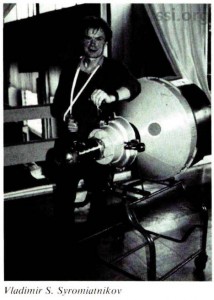
On Friday, May 17 Professor Vladimir S. Syromiatnikov, Chief of the Electromechanical Engineering Branch for Large Deployable Structures, (a division of NPO Energia), will make a luncheon presentation. The presentation will include descriptions of the deploying and docking of large Soviet space structures.
Following the presentation Syromiatnikov will be available to autograph copies of his two books, Spacecraft Docking Devices and Manned Spacecraft. These books must be purchased in advance through the Space Studies Institute.
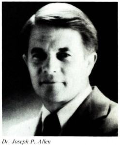
Dr. Joseph P. Allen has agreed to be the guest speaker for the banquet to be held Friday, May 17. He will discuss the “Report of the Advisory Committee on the Future of the US Space Program,” better known as the report of the Augustine Commission.
The banquet will be held at the Ramada Inn, Princeton. There may be limited extra tickets for the banquet; if you are interested in attending the banquet, but cannot attend the entire conference, please contact Barbara Faughnan at the SSI office.
SSI/Princeton Conference on Space Manufacturing
May 15-18, 1991
Woodrow Wilson School
Princeton University
Registration for the SSI/Princeton Conference is now underway. The registration fee for the Conference is $320. This fee covers all formal sessions and meals associated with the Conference. It also includes a copy of the proceedings which will be published by AIAA in hardcover format.
The Compri Hotel has been selected as the Conference Headquarters, and Continental Airlines is the official Conference airline. To register for the Conference or obtain more information on special airline fares and hotel rates, please contact the SSI office during regular business hours.
EXCERPTS FROM: AN ALUMINUM SALVAGE STATION FOR THE EXTERNAL TANK (ASSET)
[[librarian note: the full Master’s thesis is available as a readable “best copy” pdf from The Defense Technical Information Center servers. Use this link: http://oai.dtic.mil/oai/oai?verb=getRecord&metadataPrefix=html&identifier=ADA230841]]
1. INTRODUCTION
SSI, in identifying the need for construction material at low-Earth orbit (LEO), approached the Air Force Institute of Technology’s Aeronautics and Astronautics Department with the question:
Can an External Tank (ET) be reduced to a useful raw material in a cost competitive manner when compared with launching the same material from the Earth’s surface?
By taking a systems engineering approach to this question, a design team of one Army and four Air Force Officers have answered that question with a resounding Yes.
While the idea of salvaging the ET is not new, the techniques developed in this study represent a fresh look and a novel approach at actual tank reduction. Three scenarios are developed to allow on-orbit salvage of the ET aluminum.
An overall system level study was initiated to identify the key technologies and hardware components required to carry out the salvage operation. These included cutting technologies, the provision of power for all phases of the operation, orbital maintenance hardware requirements, Extra-Vehicular Activity (EVA) technologies, and other special tooling requirements.
A process simulation, using SLAM II (Simulation Language for Alternative Modeling) as the simulation language, is developed to estimate the tank reduction timelines and peak power requirements. A trade study is then conducted to identify viable candidates as sources of power generation. A thermal model is developed and the thermal impacts of on-orbit salvage are included in all scenarios.
The necessary tools to accomplish the tasks of initial cutting, product/tool transportation, spray on foam insulation (SOFI) removal, and product storage are developed. The tool design is straightforward and well within today’s state of the art. An orbital mechanics model is developed to estimate the orbital decay of the facility and the orbital lifetime of any debris which may be generated during the salvage operation. The model also produces estimates of the facility’s annual fuel requirements.
A probabilistic cost model is developed and the life cycle costs are projected based upon reducing four tanks per year. It is shown that more than 52,000 pounds of readily usable construction material in the form of I-beams and plates can be salvaged on an annual basis in a manner that is cost-effective when compared with equivalent products launched from Earth.
Scenario Development – Overview
Scenario I – Automated Reduction
The distinguishing characteristics of Scenario 1 are the pre-installation of a centerline track down the middle of the LH2 tank and cuts out pieces of stringer and plate (which will still have the SOFI attached). An extending prismatic-revolute-prismatic robot arm is attached to a trolley mounted on the centerline track to provide product/tool transport. The robot arm initially picks up the composite (plate, I-beam, and SOFI) strips as they are cut out and carries them to the SOFI workstation. The SOFI workstation removes the SOFI, stores the removed SOFI, provides a secondary cut to separate the stringers from the plate, and stores the separated products in their respective containment equipment.
The process is repeated until an entire barrel section of the LH2 tank has been cut up into a pre-designated number of pieces. Portions of each barrel section will be left to maintain the structural integrity of the overall facility. It will be shown that some 6,125 linear feet of stringers and 4,850 ft2 of plate can be salvaged from a single tank within 40.8 hours of actual reduction time over the course of a 6.3 day orbiter mission. The 40.8 hours would be preceded by 16 hours of 2 man EVA and the peak power required during the salvage operation would not exceed 11.5 kW.
Scenario 2 – Manned Reduction
The distinguishing characteristics of Scenario 2 are the absence of a centerline track and the presence of astronauts to perform the actual reduction operation. EVA crews of three persons will be required. Astronauts are used instead of automated tools to perform all tasks associated with product/tool transport.
Two primary cutters are used instead of one and two barrel sections of the LH2 tank are reduced simultaneously. Astronauts will transport the composite strips, load the piece parts into the workstation, and store the products in separate containers at the output of the SOFI workstation.
With minor exceptions, the same basic products will be salvaged; however, the salvage task is much more EVA intensive. The actual reduction time is 23 hours, but (due to the required rest time between EVA’s) the overall orbiter mission extends to 8.3 days. A total of 63 equivalent 2 man EVA hours would be required and the peak power requirement during the salvage operation would increase to 18.85 kW.
Scenario 3 – Rendezvous With Space Station Freedom
The distinguishing characteristic of Scenario 3 is the rendezvous and subsequent sale of electrical power at Space Station Freedom (SSF). Scenario 3 incorporates salvage at a lower altitude (via Scenario 1 or 2) prior to rendezvous. The only physically distinguishable features of Scenario 3 are the duplication of a SSF power module on the External Tank and the effects this larger system (from a weight and drag standpoint) has on the overall ASSET facility.
Product Summary
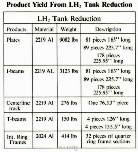
The baseline product yield for Scenario 1 is shown in Table 1. The yield for Scenario 2 is very similar except there are no centerline track or cross bars (T-beams) to salvage. Additional yield from the LO2 tank was also considered and that data is provided in the report.
Scenario 1 – Automated Reduction
Overview
Scenario 1 features automated reduction. Tools have been developed to carry out all aspects of the salvage operation and the ASSET facility will be unmanned during the actual reduction operation. The distinguishing characteristics of Scenario 1 are the pre-night installation of a centerline track (mounted longitudinally down the center of the LH2 tank) and the absence of astronauts during the actual reduction operation.
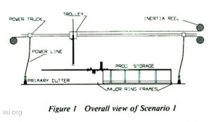
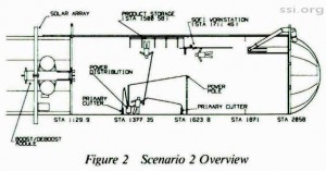
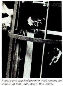
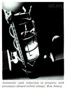
Reduction starts in the aft barrel section (see Figure 2). A primary cutter rides the stringers (I-beams) and cuts out a composite strip composed of plate, I-beam, and SOFI. The centerline track is utilized to mount a robot arm/trolley combination which moves the primary cutter in the radial direction and transports the composite strips (see Figure 1) in the longitudinal direction once they have been cut out. The robot arm will insert the composite strips into the SOFI workstation.
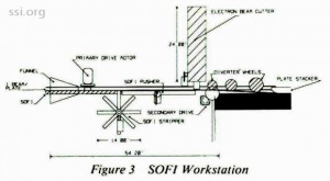
The SOFI workstation (see Figure 3) removes the SOFI, stores the removed SOFI, provides a secondary cut to separate the Ibeam from the plate, and stores the I-beam and plate in separate storage/ containment equipment.
An overall view of the Scenario I operation is shown in Figure 1. The pre-installed centerline track provides power to the primary cutter by means of a free-sliding power truck. The trolley receives its power from the forward area of the tank via a cable fed through an inertia reel device. This power connection to the trolley is attached to the non-rotating portion of the trolley. The extending robot arms attached to the rotating portion of the trolley will pick up the composite strips as they are cut out of the LH2 barrel and insert them into the SOFI workstation input funnel which is approximately 4 feet inward from the outer surface of the tank.
Once the SOFI has been removed and secondary cuts have been made to separate the I-beam from the plate, the separated products are stored between the two major ring frames as shown.
The LH2 tank is reduced to a ‘birdcage’ structure (see Figure) in I. 7 days (40. 77 hours). The peak load demand is 11.5 kW and 13,045 pounds of readily usable aluminum have been salvaged.
Scenario 2 – Manned Reduction
Overview
Scenario 2 features manned reduction. The distinguishing characteristics of Scenario 2 are the absence of a centerline track and the fact that astronauts will be present during the actual salvage operation. In fact, EVA crews of three persons are required during the salvage operation.
The major change in philosophy between Scenario I and Scenario 2 is that astronauts now perform all transport tasks. Humans are used to move cutters, transport piece parts, load SOFI workstations, and store products. The three crew members will be designated as cutter, loader, or stacker and their functions are explained below.
The same basic tools developed for Scenario I will be used again for Scenario 2. There is no change to the design of the primary cutter, but Scenario 2 uses two primary cutters and will reduce two barrel sections of the LH2 tank simultaneously. Although the cutter design is unchanged, the cutting scheme had to be modified. The cutters from two barrel sections must end up at a common point so they can be moved (radially) by a single person. This person is designated as the cutter.
The input side of the SOFI workstation is unchanged, except the piece parts are now loaded manually by an astronaut appropriately designated as the loader. The actual stripping operation is unchanged, but the output to the SOFI workstation has been simplified. The separated I-beams and plate are no longer automatically stored; rather an astronaut (appropriately designated as the stacker) will place the products in separate storage containers.
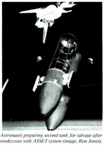
One new device was developed to support Scenario 2, a seat which is installed on one of two major ring frames. (The seat is shown in Figure 2.) Input power is routed into the rear of the seat and distributed out to the two primary cutters (one on either side of the major ring frame). An astronaut (who may or may not be strapped into this seat) will move the cutters (radially) and hand off piece parts as they are cut out to one of the two remaining astronauts. A brake is provided to lock the seat at a certain location. The astronaut releases the brake and provides his own power to move in the radial direction.
Reduction starts in the two forward barrel sections of the LH2 tank. As piece parts are cut out, the astronaut (cutter) in the work seat (initially installed at major ring frame 1377.35) will pick up and hand off piece parts to the astronaut (stacker) stationed at the output of the SOFI workstation (approximately station 1500.58). The part is then handed off to the 3rd astronaut (loader) stationed at the input to the SOFI workstation (approximately station 1711.46) who, in turn, will load the piece part into the SOFI workstation.
The stacker will move the parts into storage containers very similar to those used in Scenario 1. This person will be required to handle all piece parts twice while the two forward barrels of the LH2 tank are being reduced. The stacker has the highest workload, but could trade off with the loader if fatigue becomes a factor. The stacker is required even if the output of the SOFI workstation had been left in its Scenario 1 configuration since pieces cut out of the forward barrel sections are of insufficient length to be handed directly to the loader.
Once the two forward barrels of the LH2 tank have been reduced, the workseat will be moved from station 1377.35 to station 1871. Power cables to the two primary cutters are disconnected prior to transport. The workseat is only moved once in the longitudinal direction during Scenario 2 reduction. When the workseat has been reinstalled, the two primary cutters moved from barrels three and four to barrels one and two, and power cables reconnected to the primary cutters, reduction of the two aft barrels of the LH2 tank is ready to begin.
As piece parts are cut out of the two aft barrels, the astronaut in the workseat (cutter) picks them up and hands them off to the loader at the input to the SOFI workstation. Although the piece parts from barrel one are shorter, they are still of sufficient length to be handed off from the workseat. The stacker is not required to handle piece parts twice while the aft barrels are being reduced.
The LH2 tank is again reduced to a ‘birdcage’ structure (as in Scenario 1). The actual reduction time for Scenario 2 is 23 hours (as opposed to 40. 77 hours for Scenario 1). However, since crew rest is required between EVA’s the actual mission timeline is longer in Scenario 2. Eight hour EVA’s with 16 hours of rest between EVA’s are assumed.
The peak power requirements for Scenario 2 are higher since multiple cutters are operated simultaneously. The peak load demand is 18.85 kW (as opposed to 11.5 kW for Scenario 1), due to the fact that no centerline track and associated cross bars are available for salvage.
Conclusions and Recommendations
1. It is clear that the External Tank can be reduced lo readily usable construction material.
• The tool design is a simple, low risk development effort. The electron beam cutters, boost/deboost modules, and photovoltaic arrays are essentially off-the-shelf purchases. There are no foreseen technical hurdles.
• The 13,045 lbs of salvaged products (from a single LH2 tank) are readily usable.
(a) 6,125.8 linear feet (3,123 lbs) of I-beams.
(b) 4,859.5 ft 2 (9,082 lbs) of plate.
(c) A single 76.33 ft centerline track (276 lbs).
(d) Miscellaneous other hardware (564 lbs).
2. The External Tank can be reduced in a cost effective manner.
• Automated scenarios are more competitive than man-tended scenarios. This trend will continue if the tool design is allowed to remain simple. The temptation to push the state of the art in the tool design should be resisted.
• It is clear that Scenario 1, with the less efficient array, is the most cost competitive method of operation. Scenario 3-1 is a close second and may warrant consideration. The principal reason Scenario 3-1 is not more competitive (which may be somewhat of a surprise due to the increased revenue stream realized by the sale of power) is due to the risks associated with rendezvous at SSF. The operations costs have been skewed to the high end in the cost model, which is a conservative approach.
3. LO2 barrel salvage appears to be well worth the effort.
• When LO2 barrel salvage is included, one becomes 90% confident that the salvage operation is cheaper than the alternative of launching similar products from Earth.
4. Under the assumption of four LH2 tanks salvaged per year, ASSET could provide the equivalent of a dedicated STS launch on a yearly basis.
• This effectively increases the NASA launch rate, with minimal impact on current launch schedules, and can be done profitably over a 10-year operational life.
©space studies institute
NEXT: 1992 January-February (Are we progressing? Lunar Solar. 3d Printing)

