
SPACE STUDIES INSTITUTE
P.O. BOX 82
PRINCETON, NEW JERSEY 08542
[[librarian note: This address is here, as it was in the original printed newsletter, for historical reasons. It is no longer the physical address of SSI. For contributions, please see this page]]
SSI UPDATE
THE HIGH FRONTIER® NEWSLETTER
VOLUME XIX ISSUE 5 SEPTEMBER/OCTOBER 1993
FROM THE SSI HEADQUARTERS
Thank You to the Membership
The membership of SSI has always been SSI’s greatest asset throughout its history, and remains so as we celebrate our 16th anniversary. SSI members and Senior Associates have given creative, intellectual and financial support to the Institute. On behalf of the SSI Board of Directors and the staff, I would like to thank you for all of your generous contributions which have made possible all the projects discussed below.
Brochure
Enclosed with this newsletter you will find a copy of SSI’s new brochure. It is an example of a collaboration by several members of the SSI family. The artwork was created by Senior Associate, Mark Martel, with technical support by Dr. Seth Potter. The text was written by the SSI staff with the editorial assistance of several SSI Directors. And now I would like to ask for your involvement. Please share this brochure with a friend or colleague. To realize our goals and dreams for 1994, we must increase our strength. If you have names and addresses of friends that you would like us to send the brochure to, please forward them to SSI by letter or fax. We will check our membership list and if the person is not already a member, we will promptly send them a brochure and membership reply card.
Speakers’ Bureau
SSI has organized a Speakers’ Bureau under the director of Senior Associate, Jay Haines. He has described the program in an article on page 6 of this newsletter. We appreciate the donation of his time for this project, and we encourage you to use the service to arrange for a speaker in your area. We also encourage you to sign up as a presenter. To succeed, we must make space seltlements, space industry and space-based power household words.
Research Update
The article, Surmounting Technological Denial – in low-Cost Access to Space, by Leik Myrabo of Rensselaer Polytechnic Institute, gives a summary of the work he completed this past summer on the Lightcraft Project with the collaboration of Dr. Yuri Raizer from Russia. This article (page 4) focuses on the laser portion of their efforts. Dr. Myrabo will update you on the microwave portion in an upcoming issue.
In a letter written by Myrabo in July, he wrote, “What has it meant to me now that SSI has somehow managed to team me up with a world-renouned author, scientist and winner of the Lenin Prize, the highest scientific award given in Russia? I am nearly dumbfounded when I attempt to capture my feelings with words … The professional in me knows that publishing these new research results with Raizer will open up a world of new opportunities. I doubt that I could have ever imagined the experience or the outcome of collaborating with this friendly, wise and steadfast scientist, who is filled with much of the knowledge that can propel Lightcraft (and low-cost access to space) into reality. Thank you SSI!”
Bettie Greber
APPLICATION OF CERAMIC-CERAMIC JOINING TO IN-SITU RESOURCES IN THE CONSTRUCTION OF LARGE LUNAR STRUCTURES
R.S. Crockett and B.D. Fobes
Department of Materials Science and Engineering
University of Arizona
Tucson AZ 85721
Abstract
Results are reported from a series of experiments designed to explore the suitability, durability and applicability of various joining techniques proposed for building large lunar structures utilizing lunar soil as raw material. The engineering challenges faced in the task of building such structures, and the various joining techniques available, are reviewed in detail as an introduction to the experiments and their results.
Building large structures from the products of lunar soil promises to be a key means of reducing dependence on Earth as a lunar base evolves towards self-sufficiency. Designs for large pressurized habitation modules1, unpressurized storage facilities2, and ground preparation such as roadways or landing pads3 have all been presented as potential applications for lunar-produced structural components. Many basic material science issues, however, still need addresing before viable system studies can be performed.
Several processes have been proposed for producing structural materials from lunar resource , including hot-pressing (sintering) the soil, melting the soil and cooling in molds to produce cast basalt components, applying heat-treatment cycles to melted soil under a more controlled process to produce glass and glass-ceramics, and direct melting of lunar soil in place to produce continuous glass-like surfaces.
The maximum size of a single cast will be on the order of tens of centimeters per side, limited by stresses induced during cooling. The extent to which unusual shapes can be produced will also be restricted by processing limitations. Thus large structures built using lunar resources will require joining of the individual cast components. Additionally, the structure must be sealed if it is to hold a pressure atmosphere. Both joining and sealing of components can potentially be accomplished using entirely indigenous materials by taking advantage of the glass-forming properties of lunar soil.
The products of unrefined lunar soil will be ceramic materials; ceramic-ceramic joining techniques used for structural and electronic applications on Earth are thus a logical starting point in developing joining methods for lunar applications. The following options for joining all make use of available lunar resources:
Mechanical Joining: Simple Stacking/Interlocking Blocks
Individual components are stacked in a tongue-in-groove type arrangement. Gravity, external loading, the geometry of the blocks, and forces from internal pressure are balanced to produce a stable structure. By adding gaskets, the structure can be sealed by compression from internal pressure, but gasket material must be manufactured locally or brought from Earth.
Key Issues
• Requires complex shapes of cast components to provide interlocking.
• Structural integrity depends on shear and tensile strength of “tongue.”
• Low gravity of Moon does not provide a large stabilizing force, possibly limiting this option to low-pressure or unpressurized structures only.
• Compression sealing requires interlocking of blocks to support higher loads (places more burden on the strength of cast lunar components/interlocking joint).
• Verification and maintenance of seals will increase astronaut workload.
Fusion Welding
This method uses heat (potentially in the form of a concentrated solar flux) to melt the surface of adjoining blocks so they fuse together. Fusion welding can be used for interlocking or simple flush-surfaced blocks, but the surfaces must be closely butted together. If structure is pressurized, an internal bladder or spray seal will most likely be required.
Key Issues
• Resulting joining will be relatively brittle.
• If the coefficient of thermal expansion of the material formed at the interface is different from that of the blocks, the fused zone will be subject to high stress and may crack as it shrinks during cooling.
• Ability to melt surface of blocks will vary dramatically with the material being fused.
Heat transfer through the material must be low enough to maintain sufficient surface temperatures, but high enough to avoid thermal shock – this may limit the practicality of this method to the joining of sintered blocks.
• Preheating of blocks may be required to minimize thermal shock.
Glazing: Heat Melt
Similar to the fusion welding technique, but with melted lunar soil acting as the interface material. Soil is packed between components and heated, melting to form a glass bond.
Key Issues
• Lunar soil is an extremely effective thermal insulator at high temperatures, where heat transfer occurs by radiation. If direct solar heating is used, only the top few mm of soil will melt to form a useful bond unless additional heat transport mechanisms are introduced.
• Vaporization will occur in high vacuum environment during heating, changing the composition of the melt.
• Joint will become highly stressed due to change in volume during cooling unless the joint is annealed (higher processing complexity).
• Resulting joint will be relatively brittle.
• Preheating of blocks may be required to minimize thermal shock.
Glazing: Cast Joining
A high temperature (~1600 C) melt of the same material is poured between components. This re-melts the outer layer of the blocks, forming a continuous interface gradient. Ideally, the joint formed will be as strong as the components themselves.
Key Issues
• Requires more complex shapes of cast to provide surface for melt containment.
• Forms are required during pouring, which must withstand the high temperatures involved.
• Vaporization will occur in high vacuum environment during heating, changing the composition of the melt.
• Heat content must be sufficient to melt the block surfaces.
• Method may be limited to small joints, as melt will tend to cool rapidly, becoming extremely viscous before filling the entire void.
• Cooling cycle must be controlled to allow for an acceptable interface gradient and matching of mechanical properties.
• Preheating of blocks may be required to minimize thermal shock.
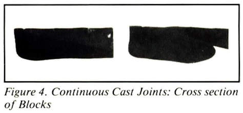
Continuous Cast
This is an extension of the Cast Joining method where each block is cast in place during structure construction to form a single unbroken surface. The melt for a new “block” is cast in direct contact with adjacent blocks. As new cast is cooling, surfaces of existing blocks will re-melt, forming a continuous interface gradient between components. May not require internal bladder or spray seal.
Key Issues
• Forms are required during pouring, which must withstand high temperature of the melt.
• Cooling cycle must be controlled to allow for an acceptable interface gradient and matching of mechanical properties.
• Vaporization will occur in high vacuum environment during heating, changing the composition of the melt.
• Preheating of existing blocks will most likely be required to minimize thermal shock.
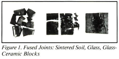
To evaluate these methods, potential joints were experimentally tested. These experiments were limited to techniques involving direct manipulation of lunar soil and performed on small block sample sizes. Simulated lunar soil was processed into sintered soil, glass, and glass-ceramic blocks. These samples were cut and then rejoined using four methods: fusing, heat melt, cast joining, and continual cast, with the effect of preheating and cooling profiles evaluated to identify potential pitfalls and key issues.
Both the block samples and the joining material were prepared from the same batch of simulated lunar soil. The composition of Apollo 15 lunar soil was chemically reproduced (except for trace elements) from 99.5+% pure oxides in the following weight percentages:
Table l. Simulated Lunar Soil Composition
(modeled after Apollo 15)
| Component | Formula | Wt % |
|---|---|---|
| Silica | SIO2 | 47.0 |
| Alumina | AI2O3 | 14.7 |
| Ferrous Oxide | Fe2O3* | 14.4 |
| Magnesia | MgO | 11.6 |
| Calcium Oxide | CaO** | 10.9 |
| Titania | TIO2 | 1.4 |
*- Actual lunar soil contains the reduced state, FeO
**- Produced from reaction: CaCO3 > CaO + C02
The University of Arizona’s 1.5m solar furnace5, 6 was used to provide a solar flux for the fusing and heat melt methods, and an electric furn ace was used to melt the soil for the cast joint and continuous cast methods. Successful joints were cross-sectioned, with one half broken through four-point bending on a mechanical testing machine.
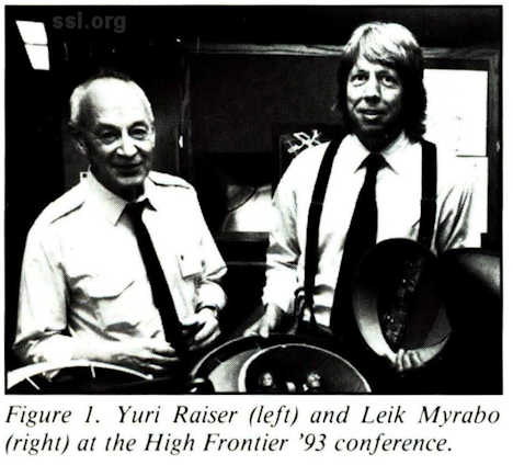
As seen in figures 1-4, only the sintered samples consistently survived the joining process. Thermal shock and residual stress in the blocks were clearly the limiting factors in this set of experiments. A material’s ability to survive thermal shock is a matter of both avoiding fracture upon a high temperature gradient, and suppressing propagation of any cracks that do form. The equation, below, shows that the allowable temperature drop without causing fracture is a function of Ri, a material’s resistance to thermal stress, and S, a geometric shape factor7.
High fracture stress, low modulus of elasticity (E), and low coefficient of thermal expansion (a) all tend to increase the value of Ri, and thus are the factors which limit crack initiation.
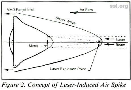
This equation shows a material’s resistance to crack propagation (Rp). Cracks are less likely to propagate in materials with low strengths and high elastic moduli, or in porous/non-homogeneous materials where the energy of cracks initiated at the surface can be dissipated by pores or grain boundaries:
This is often a direct trade-off, then between strength and thermal shock resistance. Of the samples used in the experiment, the sintered blocks consistently survived thermal shock because of their high porosity (~60%), which prevented crack propagation. The glass and glass-ceramic blocks, however, had reactions more typical of brittle ceramic materials, fracturing dramatically upon sudden temperature changes or during later cutting as a result of residual stress. Thermal shock was reduced, but not eliminated, by preheating the blocks to 600°C. To eliminate structural damage to brittle materials, preheating temperatures will have to be closer to the actual temperature of the melt used in joining.
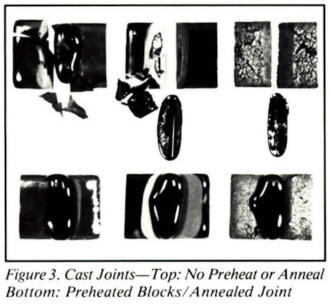
The temperature of the surfaces being joined also plays an important role in ability to bond. In the glazing process, heat transferred from the melt acts to raise the surface of the material to a temperature sufficient for bonding. Because the same composition is used for both the components and the joining medium in these methods, the final temperature must be fairly close to the composition’s melting temperature to ensure a good bond. Without preheat, the melt may not have enough heat content to melt the block surface (see Figure 3, top photo).
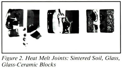
Another consideration in elevating the temperature of surfaces prior to bonding is the observed effect of temperature on the surface energy of the samples. As can be seen in the heat melt experiments (Figure 2), melted soil “balled up” without flowing into the joint; the high energy of the glass melt-to-sample interface prevented wetting, and thus any significant bond, until the surface of the blocks was nearly the same temperature as that of the melt. A final, though critical, effect of block temperature is that of maintaining low viscosity of the glass melt. In extending these method to a larger scale where the joining material must flow over long distances, cooling rate and resulting viscosity increase will be critical.
A key limitation to any method employing a solar flux is the opaqueness of melted lunar soil. As soon as a melt forms under a solar flux, the opaque surface layer blocks any further radiative heat transfer. In agreement with previou experiments8, it was found that only the top few mm could be melted by direct solar radiation. This can also explain the difficulty of melting the surface of the glass and glass-ceramic samples more rapidly under a direct solar flux, possibly due to a combination of a higher initial absorbance coefficient, and because of the high porosity of the sintered sample’s surface.
Methods of joining lunar-produced structural components using indigenous resources cannot be developed or evaluated independent of the materials to be joined. There is a tradeoff in material selection when receptiveness to joining by these methods is considered; the set of properties considered optimum for use as a structural material may not be the same as that for successful joining. Glass and glassceramics are potentially strong materials, but have low thermal shock resistance and are harder to work with under a solar flux. Although the sintered material was weaker, it was by far the most receptive to the types of joining methods studied due to its combination of resistance to thermal shock and ease of use in direct solar melting. While procedures such as pre-and-post heat treatment can reduce the impacts of the joining, they also tend to increase the complexity of the process. What is needed, then, is to find the balance between practicality as a structural material and ease of joining. At this point, fusion welding of sintered regolith appears to be a promising combination, and it should be further investigated.
Acknowledgements:
The authors would like to thank Ms. Michelle Minitti for her assistance with sample preparation and interpretation of results. This work was supported by McDonnell Douglas and by the NASA/UA Space Engineering Research Center’s Industrial Affiliates.
Editor’s Note: Robert Crocket was the recipient of the Muhlmann Award, presented by Space Studies Institute, at the recent High Frontier conference.
References
1. J.A. Happel, K. Williams, and B. Shing, “Prototype Lunar Base Construction Using Indigenous Materials,” pp. 112-122 in Engineering Construction and Operations in Space III: Proceedings of Space 92. Edited by W.Z. Sadeh, S. Sture, and R.J. Miller, 1992.
2. P. Land, “Lunar Base Design,” pp. 363-373 in Lunar Bases and Space Activities of the 21st Century. Edited by W.W. Mendell, Lunar and Planetary Institute, Houston, TX, 1985.
3. M. Magoffin and K. Stone, “Applications and Design Issues for a Lunar SurfaceBased Mobile Solar Concentrator,” 10th Biennial Space Studies Institute/Princeton Conference on Space Manufacturing, Princeton, New Jersey, May 15-18, 1991.
4. A. Binder, M. Culp, and L. Troups, “Lunar Derived Construction Materials: Cast Basalt,” pp. 117-122 in Engineering Construction and Operations in Space II: Proceedings of Space 90. Edited by S. Johnson and J. Wetzel, 1990.
5. W.M. Tuddenham, “A Solar Furnace for Research in Nonferrous Metallurgy,”
Journal of Solar Energy Science and Engineering, 1 [2,3] (1957) .
6. T .M. Lambright, “An Analysis of Possible Solar Energy Utilization in the Metallurgical Industries,” M.S. Thesis, University of Arizona, 1976.
7. W.D. Kingery, H.K. Bowen, and D.R. Uhlmann, Introduction to Ceramics, Wiley, New York, 1976.
8. B. Fabes, W. Poisl, A. Beck, and L. Raymond, “Processing and Properties of Lunar Ceramics,” AIAA Space Programs and Technology Conferences, Huntsville, AL, March 24-27, 1992.
PROCEEDINGS
Space Manufacturing 9
The High Frontier: Accession, Development and Utilization
The complete proceedings of the May, 1993 High Frontier Conference: Bringing the Vision of Space into Reality is available at a special price of $60.00 to SSI or AIAA members.
The cover illustrates a Solar Power Satellite in space with the inset showing how the rectennae or Earth-based receiving station would appear. The creative energies which went into the production of this cover represents a group effort of SSI Senior Associate volunteers. The painting was done by Mark Martel of Dayton, Ohio with scientific input from Seth Potter of New York City. Ben Hanbicki of Doylestown, Pennsylvania made the CAD schematic of the SPS, and Peter Thorpe of New York City designed the layout and cover graphics.
Those wishing to place an order may do so by sending a check, money order, VISA or MasterCard number and expiration date to: SSI, P.O. Box 82, Princeton, NJ 08542, or, for credit card orders, by calling xxx-xxx-xxxx.
UPDATE ON THE GERARD K. O’NEILL MEMORIAL LIBRARY
With invaluable help from Carole and Morris Hornik, the Gerard K. O’Neill Memorial Library became a reality this summer. The Horniks, on several weekend visits to Princeton, sorted and classified hundreds of books (both fiction and non-fiction), reports, research studies, technical literature, conference proceedings, periodicals, government and NASA documents and then selected over 450 entries for the Library – all in keeping with the philosophy of advancing the concepts of the High Frontier.
Using the Horniks’ computer database and our own lnmagic library software, key data was entered for each document including title, author, illustrator, sponsoring organization, publisher, publication date, a brief summary of the contents, and O’Neill reference pages where listed. Special facts or notes were entered into a field created for that purpose, and each piece was given a unique record number for easy identification and location.
Information on asteroids, lunar bases, space manufacturing, mining of space resources, solar power satellites, mass drivers, space construction and habitation, materials processing and much more can be found in the Library. There is a sizeable collection of science fiction novels (“colony fiction”) incorporating the concepts and technology created by Gerard O’Neill, as well as a small selection of space books for young readers.
The Library is currently set up for inhouse use only. You are welcome to come to the SSI office and browse or research, but we cannot release original material to you. If you decide to visit, we would appreciate your calling to make an appointment.
We continue to seek donations to the Gerard K. O’Neill Memorial Library. If you have or know of someone who has appropriate material, please write to the SSI office with a description of the items and your reasons for its inclusion in the Library before sending anything to us.
1) Works by Gerard K. O’Neill, whether written, transcribed from presentations, audio or video taped, or filmed; to indicate popularity or longevity, multiple editions will be represented.
2) Works referring to Gerard K. O’Neill, namely those citing his space concepts (but also those that are of biographical interest).
3) Works that clearly make use of the high frontier concepts of Gerard K. O’Neill, but fail to credit him by name.
4) Precursor works to those by Gerard K. O’Neill, of two types:
a) Those that display the consensus on space before O’Neill;
b) Those that indicate earlier concepts of the High Frontier.
RESEARCH UPDATE
Surmounting Technological Denial in Low Cost Access to Space
Leik N. Myrabo, RPI
Abstract: This brief article summarizes highlights from the SSI-funded Lightcraft Project. This year’s fledgling effort began as a collaborative research activity between Prof Yuri Raizer (Institute for Problems in Mechanics, Moscow, Russia) and Prof Leik Myrabo (Rensselaer Polytechnic Institute, Troy, NY). Historically, SSI has had a strong interest in exploiting the potentials of wireless power transmission using microwave frequencies, as well as low-cost access to space. The Lightcraft Project activities reported here will focus on the latest developments in Laser propulsion research for single-stage-to-orbit spacecraft. An upcoming article will emphasize companion developments in microwave-boosted Lightcraft technology.
The Lightcraft Project proposes to exploit unconventional, ultraenergetic pathways to creating advanced propulsion, structures and aerodynamics technology for tomorrow’s spacecraft. The obvious reason for this focus is that, historically, the future has rarely been changed in big ways by conventional wisdom. It often takes novel and radical concepts to trigger revolutionary steps forward. Low-cost launch systems will not magically appear just because some clever soul figures out how to increase a turbine’s efficiency by 0.2% or a chemical rocket’s specific impulse by 10 seconds. Let’s face it, we’re smashed up against the hard physical limits of chemical propulsion, and nothing revolutionary is likely to come from this familiar technology – at least until HEDM (high energy density material) propellants or some other radical avenue is opened. What we so desperately need is an efficient space transportation system that can propel us safely into orbit for the price of a common airline ticket. Otherwise, the dream of having thousands of us living and working in space within our lifetime will continue to elude us. The Lightcraft Project seeks to turn this lofty dream into hardware reality.
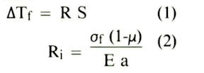
The Dream took a great leap forward last summer with the arrival of the biennial High Frontier conference, when Yuri Raizer accepted SSI’s invitation to attend this event and focused his formidable talents on Lightcraft technology (see Fig. 1). In the following five weeks, Yuri layed down the theoretical foundations for several central physical problems related to ultra energetic Lightcraft propulsion systems. The following report details the principal conclusions of our collaborative effort.
Air Spike Inlet Analysis
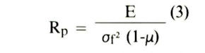
Figure 2 illustrates the concept for a novel device that enables active control of a Lightcraft’s external hypersonic aero/thermodynamics. We have decided to call it a laser (or microwave) induced Air Spike, or just ‘Air Spike’ for short. The principal function of an Air Spike is to replace the traditional sharp conical forebody normally proposed for streamlining an aerospaceplane, and precompressing the inlet air for its ‘scramjet’ engine. The Air Spike accomplishes the same objective by substituting directed energy, for mass (i.e., the mass of a sharp-nosed structure).
Why do this? Because in ultraenergetic spacecraft, power is cheap and mass is the arch enemy. Active control of external hypersonic aerodynamics enables a Lightcraft airframe to be optimized under a completely different set of rules, and permits the use of ultralight, pressurized tensile structures – in the pursuit of a minimum airframe mass solution. Hence Lightcraft aeroshells are more likely to be blunt/rounded bodies (i.e., spheres, oblate spheroid, paraboloids of revolution, cylinders, etc.). In hypersonic flight, such blunt bodies would normally produce a strong normal shockwave across their bows and experience high aerodynamic resistance. However, the Air Spike transforms the normal shock wave into a weaker oblique shock, tilted strongly aft with respect to the spacecraft forebody.
Figure 3 presents the theoretical model that Yuri used to analyze the prospects for an Air Spike – operating along an airbreathing trajectory to orbit (altitudes from sea level to 50 km, and Mach numbers from 1 to 25). For an optimal flight, spacecraft velocity must clearly increase with altitude according to some predetermined schedule. Note that the spacecraft forebody is represented by a flat plate onto which a mirror is mounted to reflect and focus the transmitted laser beam to a distance L ahead of the vehicle. A flat plate would not seem like a very good first-order approximation of a spacecraft forebody, until one realizes that the Air Spike drives most of the oncoming air radially outward toward the craft periphery – where the annular inlet of the MagnetoHydroDynamic thruster (referred to hereafter as a MHD-Fanjet) is located. Therefore, a Lightcraft advances into a hot air pocket that is nearly a vacuum, and the remaining low density air has a sound speed that is greater than the flight velocity of the spacecraft. This feature of the Air Spike insures that the entire Lightcraft forebody will think it is flying at transonic velocities – all the way to orbit! Note also that Lightcraft thermal management problems are greatly alleviated by the Air Spike because skin friction and heat transfer rates fall to relatively low levels.
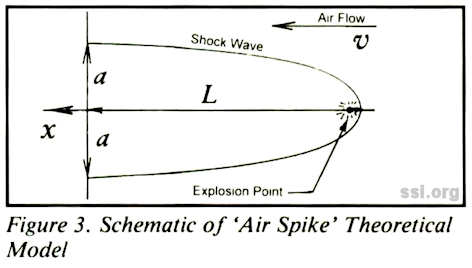
Figure 4 shows the process of forming the parabolic-shaped Air Spike using a repetitively pulsed laser beam. Note that each laser-induced detonation will create a spherical blast wave that expands very quickly at first, but thereafter slows down as the incident airflow carries the explosions aft. At the high pulse repetition frequencies required for Air Spike operation, the expansion proces closely follows a cylindrical blast wave law (centered on the flight axis). In principle, the pressure at the shock front is higher than the local atmospheric pressure so it deflects the airflow from the axial direction, and forces it to flow out over the Air Spike to the craft periphery. Table 1 gives the approximate values of laser power, pulse energy, repetition rate, pulse duration and focal distance for six points along a representative trajectory to orbit. These calculations were performed on an Air Spike suitable for a 2.56 m diameter, single-person laser-propelled Lightcraft.
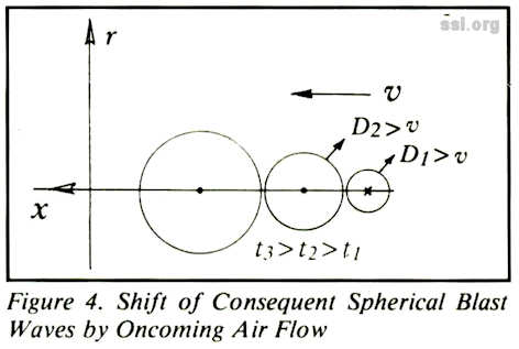
Table 1
Laser Parameters for Optimal Spike Support
| h km | M | P MW | L m | fp kHz | Wp J |
|---|---|---|---|---|---|
| 0.0 | ~1.0 | 200.0 | 0.53 | 0.62 | 3.2.105 |
| 5.6 | ~1.0 | 100 | 0.53 | 0.62 | 1.6.105 |
| 15.5 | 2.5 | 55.0 | 1.3 | 0.97 | 5.5104 |
| 30.0 | 9.5 | 21.0 | 5.0 | 14.00 | 1.5.103 |
| 48.0 | 13.0 | 2.6 | 6.9 | 26.00 | 1.0.102 |
| 62.0 | 18.0 | 0.79 | 9.5 | 50.00 | 1.6.10 |
The following conclusions were reached in the Air Spike study: If the appropriate average power, repetition rate and focal length are used, both continuous-wave (CW) and repetitively-pulsed (RP) regimes will support the Air Spike. The estimated average power decreases with altitude increase, while repetition rate and focal length increase. However, the RP regime is more favorable than the CW one, because it provides a better match with the requirements on laser-induced breakdown and detonation wave initiation at the focal point. At altitudes higher than 30 km, the laser power needed to support the spike (i.e., at least for producing ambient pressure across the forebody) is not enough to induce breakdown. With further altitude increases, the laser energy required for breakdown increases so sharply that average power exceeds the optimum value needed to support the Air Spike.
There are two apparent solutions to this problem. One option is to induce the breakdown with microwave radiation and to use a 10.6 micron infrared laser (for example) to support the Air Spike. To induce breakdown, it is advisable to use microwave radiation with optimal frequencies corresponding to the flight altitude. For the altitudes ranging from 30 km to 50 km, where it is difficult to create the breakdown using an infrared laser, the optimal radiation wavelengths fall in the range of 1 to 40 cm (i.e., the microwave band). The second option relates to increasing the time-average laser power delivered into the Air Spike at higher altitudes in order to still maintain breakdown, as well as to significantly increase the level of compression for the air entering the annular MHD thruster. With this approach, the representative 2.56 m Lightcraft might divert a constant power of 100 to 200 MW to the Air Spike, regardless of altitude – along the boost trajectory to orbit. For example, to compress the inlet air to a density ratio of 7 or 8 times ambient levels, the average power, pulse energy and focal length must be increased by 100, 10000 and 10 times respectively, at these higher altitudes-beyond the value in Table 1.
Finally, Yuri notes that his analysis is preliminary, gives a general description of the Air Spike phenomenon, provides estimates of necessary parameters, reveals the difficulties, and itemizes the important problems to be pursued in subsequent investigations. He is excited about the Air Spike concept and believes that it has an excellent chance of actually working, but has some reservations about the large power requirement. To place the 100 MW power level in perspective, it is roughly equivalent to a single turbofan aircraft engine at takeoff.
Air Plasma Formation for MHD Fanjet
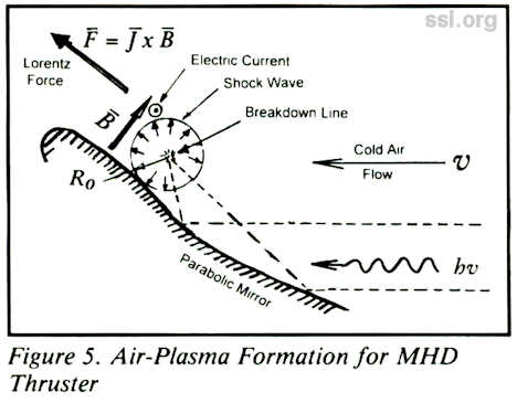
The air entering the MHD Fanjet (a Lightcraft’s hypersonic engine) should be ioinized and have an electrical conductivity high enough to carry the necessary current. In this MHD thruster, it is proposed to induce the necessary ionization using the cylindrical shock waves generated by breakdown laser pulses (and perhaps subsequent laser supported detonation waves) – see Figure 5. The linear source of this shock wave is 30 cm long, created at a distance of roughly 10 cm from the accelerator surface of a 2.5m diameter Lightcraft.
To reach comparatively high ionization levels in a shock wave, the temperature behind the front should exceed 5000 K. For example, with an ambient pressure of 1 atm, the needed temperature is reached when the pressure behind the front is 1000 atm. The ratio of pressures and temperatures in front of and behind the shock front are determined mainly by shock wave velocity, and the dependence of these parameters on the initial pressure is weak. Hence, regardless of flight altitude, the pressure ratio (PR) of 1000 should be taken as a lower limit of amplitude for a shock wave capable of providing the necessary ionization. It is also important for these particles (of air) originally ionized in the shock wave to remain in the vicinity of the rapidly expanding shock front. This critical condition becomes invalid when the ratio of pressure in the shock wave to the initial pressure drops down to 10, which is 100 times lower than the breakdown condition. After this, the front of the decaying shock wave separates from the conducting plasma which means bad news.
Knowing this condition for producing a cylindrical volume of conductive gas (i.e., airplasma that will subsequently enter the MHD thruster), and that the shock wave is produced by a linear source located at a distance of 10 cm from the body surface, it is clear that the useful diameter of this conductor should be about 20 cm. Working backwards, one determines that the initial breakdown radius (for a PR of 1000) is roughly 1 cm., centered at the focus of the primary optic. The laser pulse energy necessary to satisfy the dual conditions of a proper PR for ionization, as well as the laser-induced breakdown threshold can now be determined. One concludes that at altitudes below 20 km, the pulses providing ionization can induce breakdown. At 20 km, the focal intensity is higher than the threshold intensity.
However, above 20 km the required pulse energies are determined by the breakdown threshold, since the pulse energies providing the ionization are too low to induce breakdown. Several solutions to this problem are in evidence, including breakdown augmentation by transmitting microwave radiation (or onboard electron beams}, or using higher laser pulse energies (with the resultant higher ionization and pressures in the shock wave). For the latter case it may be possible to move the focal plane further from the surface by invoking adaptive primary optic surfaces.
The principal conclusions of this task are as follows: using repetitive laser pulses, the ionization of 20 cm diameter cylindrical volumes of air with conductivity corresponding to electron concentrations of 10 to the 13 or 14 power/ cc, can proably be produced at the inlet of the MHD thruster. Also the pulse energy and repetition rate can be chosen to optimize this process. Third, the estimates made for electron concentration, temperature and conductivity are very approximate. To be factual, this is a very complicated problem which requires detailed investigations and numerical calculations which should be pursued in a subsequent follow-on effort.
Summary and Conclusions
The technical objective of the Myrabo/Raizer collaboration on this initial phase of the SSI sponsored Lightcraft Project was to perform “first order” analytical investigations on laser-induced discharges, in support of a novel airbreathing hypersonic accelerator engine, called the MHD Fanjet. The engine is designed specifically for a beam-propelled, single-place spacecraft suitable for manned Earth-to-orbit missions. The technical approach was to first develop the theoretical foundations and then to quantify the principal laser-induced discharge phenomena that will enable successful wireless power transmission – to energize such laser propulsion converters. Finally key experiments were to be identified.
The study was comprised of four separate tasks. Roughly 50% of the effort was focused on the first task, developing the physics underlying the laser-induced Air Spike, since this device would establish the external aerodynamics over the entire vehicle. Working together, we brainstormed up two proof-of-concept experiments that could be performed at RPI. The remaining time was spent evenly divided between analyzing the air-plasma formation for the MHD thruster, the transmissivity of the Air Spike, and the conceptual design of a CW laser-sustained plasma for a 360 MW rocket gas generator (i.e., the laser-to-electric power supply).
Although more detailed analysis and computer simulations are necessary to confirm these first-order estimates, no potential showstoppers were identified in the study. Remarkably, the Air Spike inlet appeared quite promising for the Lightcraft application.
Imagine energizing this Air Spike device at sea level while punching through Mach 1. Almost like magic, an evacuated air pocket suddenly appears ahead of your spacecraft, and you feel a swift kick in the pants from the unexpected boost of 14.7 psia (standard atmospheric pressure) – delivering a force equivalent of 76 G’s over the 2.5 m afterbody heralding the start of a very quick ride to orbit!
About Yuri Raizer
Dr. Yuri P. Raizer is head of the Physical Gasdynamics Department of the Institute for Problems in Mechanics at the Russian Science Academy in Moscow. He is a world renowned author and winner of the Lenin Prize, the highest scientific aware given in Russia. Yuri has produced five major books (including Gas Discharge Physics, Laser-Induced Discharge Phenomena, Shock Waves and High Temperature Hydrodynamic Phenomena), and hundreds of technical papers in his numerous fields of interest. SSI is indeed pleased to have the technical expertise of Yuri Raiser on the Lightcraft Project.
SPEAKERS’ BUREAU
By Jay Haines
Volunteer Coordinator
One of the messages heard at the SSI Conference this past Spring was that the problem with access to space today is not technological, but marketing. All of the technology we need already exists, or will shortly. What we really need is to build a market, i.e., potential customers who demand access to space for their own purposes. These can be business persons who see space as a vehicle to make a profit or families who see space as their next vacation spot. The vision of space as a place for anyone and everyone, not just an elite astronaut corps, needs to be disseminated to build a market, a demand, for space.
SSI has formed a speakers’ bureau, a group of SSI volunteers who will give a talk when a request for a presentation comes into the SSI office. We have two prepared presentations complete with slides available. They are: living in Space (25 slides, 20 minutes) and New Harvest on the High Frontier (150 slides, 40 minutes).
We have at least one volunteer who can cover each of the following cities:
Los Angeles, CA
Boulder and Denver, CO
Washington, DC
Cedar Rapids & Waterloo, IA
Boston, MA
Baltimore, Annapolis and Frederick, MD
Mineapolis, MN
Charlotte, NC
Albany and Buffalo, NY
Cincinnati, OH
Philadelphia and York, PA
Rock Hill, SC
Alexandria, VA
Seattle and Tacoma, WA
Northwestern WI
Nova Scotia, New Brunswick,
Newfoundland and Prince Edward
Island, CANADA
If you would be willing to give a speech, and your location is not listed above or you would be willing to share the load in a listed location, please call or write me at xxxxxxxxxxxxxxxxxxxx, Lansdale, PA.
If you would like to arrange for a presentation to your local school, business or other gathering, please call the Space Studies Institute office.
MAKE YOUR OWN MASS-DRIVER
Create your own mass-driver using simple copper wire and flashlight batteries! SSI is offering easy-to-follow instructions prepared by former SSI Executive Vice President, Dr. Richard G. Woodbridge, III.
This is an excellent addition to lesson plans on electromagnetic force or an introduction to lunar bases. To order, please send $2.50 to SSI Princeton, NJ.
RESEARCH ANNOUNCED
SSI has recently announced three new research starts designed to further the development of solar power satellites and other space structures. The first project involves work on a vacuum process designed to separate lunar oxides, with an initial task of producing aluminum from lunar resources. The second project will examine thin-film solar cell design to determine what proportion of the solar collectors could be made from lunar soil. The third effort is to design affordable equipment to test the effects of power beaming. You will receive more detailed information on each project along with a request for support. Please be as generous as possible, each project is critical to reaching our goal of living and working in space. The principal researchers will update you on the results of each project in an upcoming newsletter.
©space studies institute
Next: 1993 November-December (That Famous Question, 3d Printing, DC-X flight)
