SPACE STUDIES INSTITUTE
195 Nassau Street
P.O. Box 82
Princeton, NJ 08540
[[librarian note: This address is here, as it was in the original printed newsletter, for historical reasons. It is no longer the physical address of SSI. For contributions, please see this page]]
Summer 1980
SUBSCRIBERS’ NEWSLETTER
Mass-Driver Report — Lectures — Senior Associate Program
This summer issue is primarily devoted to a detailed description of the mass-driver.
How A Mass-Driver Works: The mass-driver is a device whose capabilities are vital for the economical utilization of nonterrestrial materials in space manufacturing. For the benefit especially of new subscribers to SSI’s Newsletter, here is a brief non-technical explanation of how a mass-driver works.
[[librarian note: After reading this newsletter for historical context, see how easy it is to make your own mass driver at this page on ssi.org]]
The purpose of a mass-driver is to accelerate payloads of mass to a high velocity, by the transformation of electrical energy to the mechanical energy of motion. In one application. the payloads would be of lunar soil, the mass-driver would be mounted on the lunar surface, and it would accelerate the payloads to the escape velocity from the Moon. They would escape lunar gravity and be collected at a point in space to serve as raw material for space manufacturing.
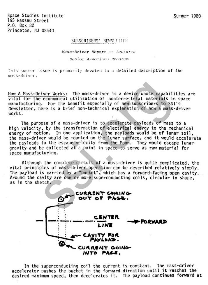
Although the complete circuit of a mass-driver is quite complicated, the vital principles of mass-driver operation can be described relatively simply. The payload is carried by a “bucket”, which has a forward-facing open cavity. Around the cavity are one or more superconducting coils, circular in shape, as in the sketch.
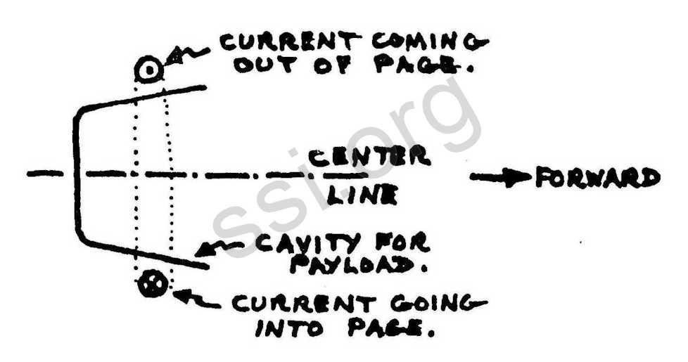
In the superconducting coil the current is constant. The mass-driver accelerator pushes the bucket in the forward direction until it reaches the desired maximum speed, then decelerates it. The payload continues forward at that speed while the bucket slows down. When the bucket is moving slow enough, it is guided around a 180 degree bend and returned to the starting point, to pick up another payload and repeats the acceleration cycle. All guidance of the bucket is by “magnetic flight” forces that do not require physical contact between the bucket and the mass-driver structure.
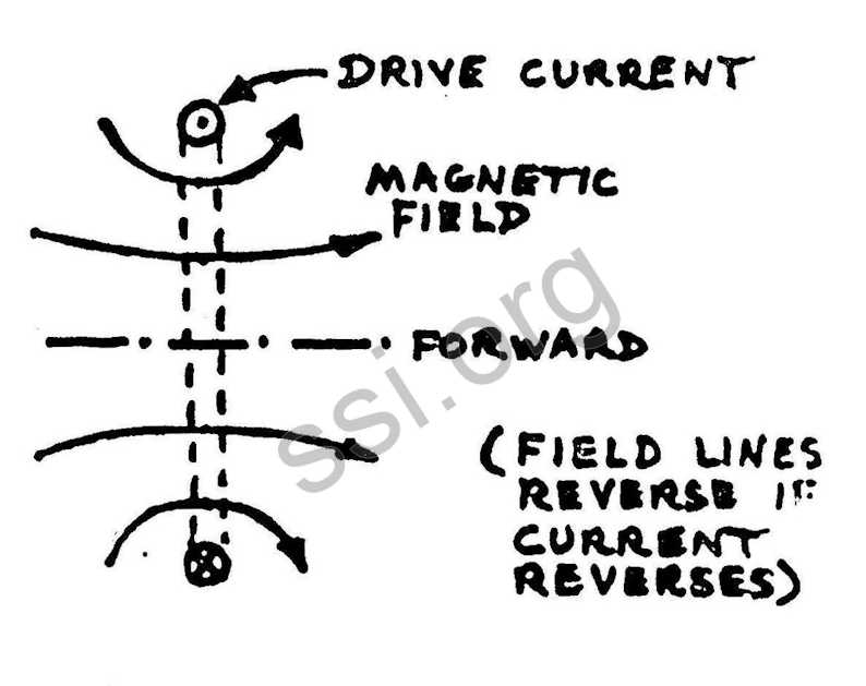
The acceleration and deceleration of the bucket occur by the successive action of a large number of “drive coils”, each of which is given a pulse of current as the bucket goes by it. Here is a picture of the magnetic field made by one drive coil:
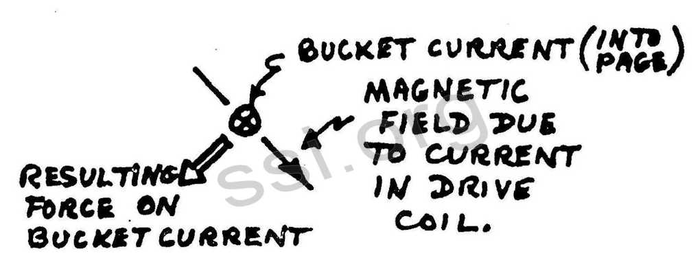
The current in the drive coil pushes on the current of the bucket coil, by a fundamental magnetic interaction that was first explored by Faraday and by Henry about 130 years ago. The force of that interaction is at right angles both to the field made by the drive coil and to the current of the bucket, as shown in this drawing.
The bucket coil is of smaller diameter than the drive coil and is centered on the same axis, as shown in the sketch to the right. When the two coils are far apart, the magnetic field due to the drive coil at the bucket coil, is very small. Therefore it doesn’t make sense to turn on the drive current when the coils are far apart, because it would just waste power without producing a useful amount of drive force.
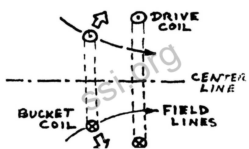
There’s another situation where it doesn’t pay to turn on the drive current: when the two coils are in the same plane. In that situation. the magnetic force would act to try to expand or compress the bucket coil, but would not provide any forward force, as you can see by the sketch on the left. So the purpose of the electrical circuitry of the mass-driver is to turn on the drive current just at the times, and in the directions, that will give the maximum amount of forward push for the least total expenditure of power.

The relationships of the drive current and the bucket position are shown in the sketch below:
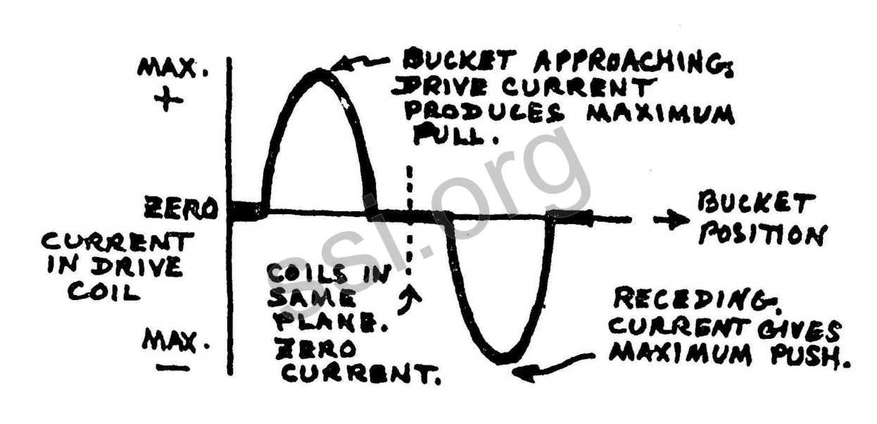
The currents have to change very quickly. For a mass-driver used to launch material from the Moon, for example (a machine with a drive-coil diameter of about 12 inches) the drive current at the high speed end, where the bucket has reached nearly full speed, has to rise to its maximum value of several thousand amperes, and then come back to zero again, in less than fifty millionths of a second. As you can see, each drive coil provides first a pull, as the bucket coil approaches, and then a push, as it recedes.
We build up a mass-driver first by adding in many more coils to make a complete “phase,” as shown roughly to scale in my sketch at the right.
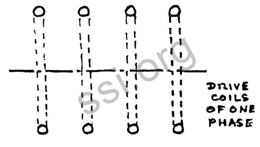
They are spaced apart just far enough so that shortly after the current in one coil has come back down to zero, the current in the next coil starts up. We do that in order to supply the current for all the coils of one phase from one source sequentially. That source is a capacitor, a set of plates on which we can store an electric charge. Between every pair of pulses we have to replenish the charge on the capacitor. That has to happen rather quickly: even for the model now under construction in our joint Princeton/M.l.T. project, we have to turn on currents of thousands of amperes, for times of less than a hundred millionths of a second, to restore the charge on the capacitor before it is time for the pulse into the next drive coil. In a full-scale mass-driver used on the Moon or in space, the recharging current is supplied from an array of solar cells.
The drive coils of one phase form a long, straight tunnel through which the bucket flies. We further complicate the mass-driver by adding now a second set of coils, called the “Phase 2” coils, interleaved with those of Phase #1. They provide a maximum forward push just in the places where the push from the Phase #1 coils goes to zero, in between its current pulses. The Phase #2 coils are supplied by their own capacitor.
When the bucket, under the action of all the coils of both phases, reaches its full velocity, we apply to it a slight braking force, so that
it disengages from the payload, which continues forward under its own momentum.
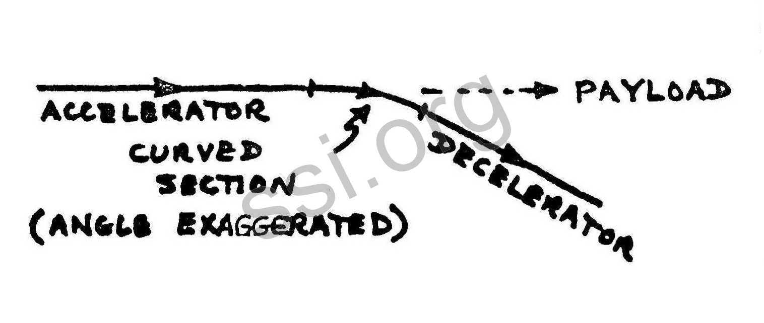
The bucket is then guided (by the forces of magnetic flight) around a slight curve, and enters the decelerator. Because of the curve, the straight line of the decelerator diverges slightly from the line of the payload as it leaves the mass-driver. The decelerator is almost identical to the accelerator. The difference is that in the decelerator the currents are all reversed, so that the bucket is slowed down. In the decelerator, the capacitor is actually charged rather than discharged by the passage of the bucket. The decelerator is a generator, while the accelerator is a motor. The decelerator takes energy out of the forward motion of the bucket and turns it into electrical energy, which is fed back to aid in the acceleration of the next bucket. In that way, the overall machine can reach a high efficiency, from 70% to 95% depending on details of the design.
There are of course many other details in the real mass-driver design, and those details are duplicated in the model now being tested. Instead of a single capacitor for each phase, there are actually many capacitors, because each short section of the machine must be “tuned” to a frequency that corresponds to the speed of the bucket, just as a radio or television set must be tuned to the frequency of the transmitting station. For the same reason the drive coils are made with many turns of wire, and the number of turns on the coils depends where they are on the machine: near the starting end the coils are wound for a low frequency, and near the high end they are made to receive and give back their currents at a high frequency. Electric-eye beams must detect the passage of the bucket as it crosses the space between each pair of drive coils, and must feed signals to logic circuitry that decide when and where to switch the currents. Every individual drive coil must be fed through controllable silicon switches (called “SCR’s” in high-power electronics jargon). Even in the model, there are more than 200 of these switches, each able to switch several thousand amperes at a voltage of a thousand volts.
Our fascination with the mass-driver stems from considerations even deeper than its utility for launching material from the Moon, important as that is. It is one of the few machines we can see that has almost no limits on its ultimate performance. In principle, a mass-driver could launch a payload to a speed almost as great as the speed of light. Such a machine would be enormously long, and it may be a century before one is built. Yet it could be, and it is very exciting for those of us who are building the model to work on a device that may be as significant, in the long run, as the first rocket or the first airplane. SSI played an essential role in the practical development of the mass-driver. Although NASA funding for mass-driver research is now at a healthy level ($250,000 in 1980), SSI stands ready to keep the work going, albeit at a slower pace, if for any reason the government funding should falter. Meanwhile, SSI’s resources are directed toward those essential items of research that would not be done at all if SSI did not exist.
Lectures:
- September 25 Purdue University, W. Lafayette, Indiana
- October 9 Arizona State University, Tempe, Arizona
- October 24-25 Tilton School, Tilton, New Hampshire
- November 13-16 University of Oklahoma, Horman, Oklahoma
- November 18 Duquesne University, Pittsburgh, Pennsylvania
- November 20 State Univ. of New York, Oneonta, New York
Publications:
Halle, Louis J. “A Hopeful Future For Mankind,” Foreign Affairs, Summer 1980. p. 1129-1136.
O’Neill, G. K. “Frontiers in Space,” PHP, Vol. 11, No. 7, Tokyo, Japan. July 1980, p. 6-22.
Senior Associate Program:
David Simpson reports rapid progress as a result of his full-time efforts this summer. In mid-August, there are 250 Senior As5ociates who have pledged $360,000 over the five-year period. Personal calls and flexible individual payment schedules both contribute to the success of the program.
Cordially,
Gerard K. O’Neill, President
NETWORK
The Chicago Society for Space Settlement’s videotape on the Space Studies Institute will be aired on Cable Channel 4, Sunday, September 28th at 10:00 p.m., in Madison, Wisconsin. Approximately 25,000 cable viewers are in the area. Many thanks to Stan Brown, a Senior Associate, for his arrangements.
Daniel Malick has been tracking the newly created Alaska Energy Center, as well as spreading the word about SSI and the High Frontier. Alaskan Subscribers interested in helping or wanting more information, contact Dan at …, or call him at (xxx) xxx-xxxx.
+ + + + + + + + + + + + + + + + + + + + + + + + + + +
Please use the form below for renewal or .to sign up a friend!
I wish to support the research and education programs of SSI for one year as a:
[ ] Sponsor ($200-500)
[ ] Contributor ($25)
[ ] Donor ($100)
[ ] Subscriber ($10)
[ ] This is a renewal
NAME
ADDRESS
CITY, STATE
ZIP CODE
(Canadian Subscribers kindly remit in U.S. funds via postal l money order or bank draft)
— All Donations are Tax Deductible -
SPACE STUDIES INSTITUTE, P.O. B0X 82. PRINCETON, NJ 08540
[[librarian note: This address is here, as it was in the original printed newsletter, for historical reasons. It is no longer the physical address of SSI. For contributions, please see this page]]
©space studies institute
